Lexus RX (RX 350L, RX450h) 2016-2024 Repair Manual: Fuel Rail Pressure Sensor (Low) / Fuel Rail Pressure Sensor "B" Circuit Short to Ground (P107A11)
DESCRIPTION
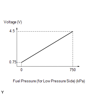
The fuel pressure sensor (for low pressure side) replaces the fuel pressure with electrical signals and outputs them to the ECM. The ECM controls the optimal fuel pressure for the operation conditions to reduce the fuel pump power consumption and improve fuel economy.
| DTC No. | Detection Item | DTC Detection Condition | Trouble Area | MIL | Memory | Note |
|---|---|---|---|---|---|---|
| P107A11 | Fuel Rail Pressure Sensor (Low) / Fuel Rail Pressure Sensor "B" Circuit Short to Ground | The fuel pressure sensor (for low pressure side) output voltage is less than 0.43 V for 3 seconds or more (1 trip detection logic). |
| Comes on | DTC stored | SAE Code: P107C |
HINT:
When this DTC is output, check the fuel pressure (for low pressure side) in the Data List. Enter the following menus: Powertrain / Engine / Data List / Fuel Pressure (Low) / Fuel Pressure 2.
| DTC No. | Fuel Pressure (Low) / Fuel Pressure 2 | Malfunction |
|---|---|---|
| P107A11 | Approximately 0 kPag |
|
If the Data List values is normal it may be due to a temporary recovery from the malfunction condition. Check for intermittent problems.
MONITOR DESCRIPTION
This DTC is stored if the fuel pressure sensor (for low pressure side) output voltage is out of the standard range due to an open or short in the sensor circuit.
MONITOR STRATEGY
| Related DTCs | P107C: Fuel rail pressure sensor range check (Low voltage) |
| Required Sensors/Components (Main) | Fuel pressure sensor (for low pressure side) |
| Required Sensors/Components (Related) | - |
| Frequency of Operation | Continuous |
| Duration | 3 seconds |
| MIL Operation | Immediate |
| Sequence of Operation | None |
TYPICAL ENABLING CONDITIONS
| Monitor runs whenever the following DTCs are not stored | None |
| All of the following conditions are met | - |
| Battery voltage | 8 V or higher |
| Engine switch | On (IG) |
| Starter | Off |
| Time after engine start | 2 seconds or more |
TYPICAL MALFUNCTION THRESHOLDS
| Fuel rail pressure sensor voltage | Less than 0.43 V |
CONFIRMATION DRIVING PATTERN
HINT:
-
After repair has been completed, clear the DTC and then check that the vehicle has returned to normal by performing the following All Readiness check procedure.
Click here
.gif)
-
When clearing the permanent DTCs, refer to the "CLEAR PERMANENT DTC" procedure.
Click here
- Connect the Techstream to the DLC3.
- Turn the engine switch on (IG).
- Turn the Techstream on.
- Clear the DTCs (even if no DTCs are stored, perform the clear DTC procedure).
- Turn the engine switch off and wait for at least 30 seconds.
- Start the engine.
- Idle the engine for 10 seconds or more [A].
- Turn the Techstream on
- Enter the following menus: Powertrain / Engine / Trouble Codes [B].
-
Read the pending DTCs.
HINT:
- If a pending DTC is output, the system is malfunctioning.
- If a pending DTC is not output, perform the following procedure.
- Enter the following menus: Powertrain / Engine / Utility / All Readiness.
- Input the DTC: P107A11.
-
Check the DTC judgment result.
Techstream Display
Description
NORMAL
- DTC judgment completed
- System normal
ABNORMAL
- DTC judgment completed
- System abnormal
INCOMPLETE
- DTC judgment not completed
- Perform driving pattern after confirming DTC enabling conditions
HINT:
- If the judgment result shows NORMAL, the system is normal.
- If the judgment result shows ABNORMAL, the system has a malfunction.
- If the judgment result is INCOMPLETE, perform steps [A] through [B] again.
-
[A] to [B]: Normal judgment procedure.
The normal judgment procedure is used to complete DTC judgment and also used when clearing permanent DTCs.
- When clearing the permanent DTCs, do not disconnect the cable from the battery terminal or attempt to clear the DTCs during this procedure, as doing so will clear the universal trip and normal judgment histories.
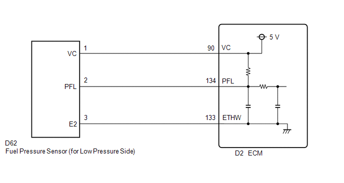
WIRING DIAGRAM
CAUTION / NOTICE / HINT
HINT:
Read freeze frame data using the Techstream. The ECM records vehicle and driving condition information as freeze frame data the moment a DTC is stored. When troubleshooting, freeze frame data can help determine if the vehicle was moving or stationary, if the engine was warmed up or not, if the air fuel ratio was lean or rich, and other data from the time the malfunction occurred.
PROCEDURE
| 1. | CHECK HARNESS AND CONNECTOR (FUEL PRESSURE SENSOR (FOR LOW PRESSURE SIDE) - ECM) |
(a) Disconnect the fuel pressure sensor (for low pressure side) connector.
(b) Disconnect the ECM connector.
(c) Measure the resistance according to the value(s) in the table below.
Standard Resistance:
| Tester Connection | Condition | Specified Condition |
|---|---|---|
| D62-1 (VC) - D2-90 (VC) | Always | Below 1 Ω |
| D62-2 (PFL) or D2-134 (PFL) - Body ground and other terminals | Always | 10 kΩ or higher |
| NG | .gif) | REPAIR OR REPLACE HARNESS OR CONNECTOR |
|
.gif)
| 2. | CHECK TERMINAL VOLTAGE (POWER SOURCE OF FUEL PRESSURE SENSOR (FOR LOW PRESSURE SIDE)) |
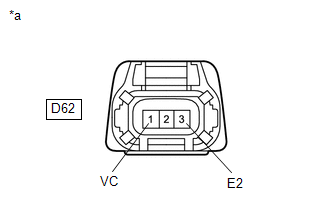
| *a | Front view of wire harness connector (to Fuel Pressure Sensor (for Low Pressure Side)) |
(a) Disconnect the fuel pressure sensor (for low pressure side) connector.
(b) Turn the engine switch on (IG).
(c) Measure the voltage according to the value(s) in the table below.
Standard Voltage:
| Tester Connection | Condition | Specified Condition |
|---|---|---|
| D62-1 (VC) - D62-3 (E2) | Engine switch on (IG) | 4.75 to 5.25 V |
HINT:
Perform "Inspection After Repair" after replacing the fuel pressure sensor (for low pressure side).
Click here
| OK | | REPLACE FUEL DELIVERY PIPE SUB-ASSEMBLY (FUEL PRESSURE SENSOR (FOR LOW PRESSURE SIDE)) |
| NG | | REPLACE ECM |
 Brake Switch "B" Circuit Short to Battery (P070312)
DESCRIPTION The stop light switch assembly is part of a duplex system that transmits two signals: STP and ST1-. These two signals are used by the ECM to monitor whether or not the brake system is work ...
 Transmission Range Sensor "A" Circuit Open (P070513,P070562)
DESCRIPTION The park/neutral position switch assembly detects the shift lever position and sends signals to the ECM. DTC No. Detection Item DTC Detection Condition Trouble Area MIL Memory ...
Other materials:
Lexus RX (RX 350L, RX450h) 2016-2024 Repair Manual > Shift Lever: Removal
REMOVAL PROCEDURE 1. SECURE VEHICLE (a) Fully apply the parking brake and chock a wheel. CAUTION:
Make sure to apply the parking brake and chock a wheel before performing this procedure.
If the vehicle is not secure and the shift lever is moved to N, the vehicle may suddenly move, possibly resu ...
Lexus RX (RX 350L, RX450h) 2016-2024 Repair Manual > Wireless Charging System: Precaution
PRECAUTION PRECAUTION FOR DISCONNECTING CABLE FROM NEGATIVE BATTERY TERMINAL NOTICE: When disconnecting the cable from the negative (-) battery terminal, initialize the following systems after the terminal is reconnected. System Name See Procedure Lane Control System Pre-collision ...
Lexus RX (RX 350L, RX450h) 2016-{YEAR} Owners Manual
- For your information
- Pictorial index
- For safety and security
- Instrument cluster
- Operation of each component
- Driving
- Lexus Display Audio system
- Interior features
- Maintenance and care
- When trouble arises
- Vehicle specifications
- For owners
Lexus RX (RX 350L, RX450h) 2016-{YEAR} Repair Manual

0.016