Lexus RX (RX 350L, RX450h) 2016-2024 Repair Manual: Security Horn Assembly(except Built-in Battery Type)
Components
COMPONENTS
ILLUSTRATION
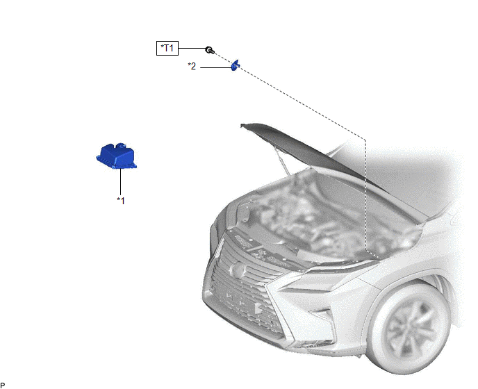
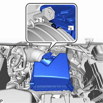
| *1 | AIR CLEANER CAP SUB-ASSEMBLY | *2 | SECURITY HORN ASSEMBLY |
.png) | N*m (kgf*cm, ft.*lbf): Specified torque | - | - |
| *T1 | for Type A: 8.3 (85, 73 in.*lbf) for Type B: 10 (102, 7) | - | - |
Removal
REMOVAL
PROCEDURE
1. REMOVE AIR CLEANER CAP SUB-ASSEMBLY
| (a) Disconnect the connector. |
|

(b) Disengage the clamp.
| (c) Disengage the 2 clamps. |
|
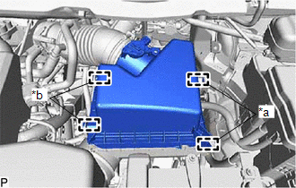
(d) Disengage the 2 guides.
| (e) Loosen the hose clamp and remove the air cleaner cap sub-assembly. |
|
2. REMOVE SECURITY HORN ASSEMBLY
| (a) Remove the bolt. |
|
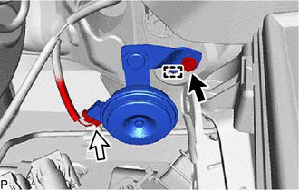
(b) Disengage the guide.
(c) Disconnect the connector to remove the security horn assembly.
Inspection
INSPECTION
PROCEDURE
1. INSPECT SECURITY HORN ASSEMBLY
| (a) Check the operation of the security horn assembly. OK:
If the result is not as specified, replace the security horn assembly. |
|

Installation
INSTALLATION
PROCEDURE
1. INSTALL SECURITY HORN ASSEMBLY
| (a) Connect the connector. |
|

(b) Engage the guide and install the security horn assembly with the bolt.
Torque:
for Type A :
8.3 N·m {85 kgf·cm, 73 in·lbf}
for Type B :
10 N·m {102 kgf·cm, 7 ft·lbf}
NOTICE:
There are three types of bolts and the tightening torque depends on the type of bolt used as shown in the illustration. Therefore, confirm the tightening torque before installing the bolt.
2. INSTALL AIR CLEANER CAP SUB-ASSEMBLY
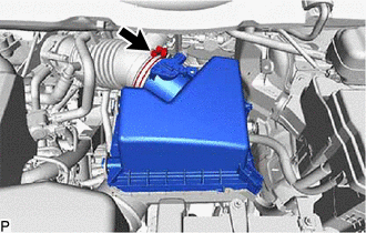
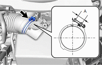
| (a) Align the rib with the hose notch as shown in the illustration and connect the air cleaner cap sub-assembly. |
|
| (b) Tighten the hose clamp as shown in the illustration. Reference Measurement:
|
|
(c) Engage the 2 guides and 2 clamps to install the air cleaner cap sub-assembly.
(d) Engage the clamp.
(e) Connect the connector.
 Installation
INSTALLATION PROCEDURE 1. INSTALL THEFT WARNING SIREN ASSEMBLY (a) Connect the connector. (b) Engage the 2 guides to install the theft warning siren assembly with the 2 bolts. (c) Engage the clamp. 2. ...

Other materials:
Lexus RX (RX 350L, RX450h) 2016-2024 Repair Manual > Sliding Roof System: Diagnostic Trouble Code Chart
DIAGNOSTIC TROUBLE CODE CHART Sliding Roof System DTC No. Detection Item Link B2341 Sensor (Motor) Failure B2342 Switch Failure B2343 Position Initialization Incomplete B2344 Position Failure ...
Lexus RX (RX 350L, RX450h) 2016-2024 Repair Manual > Door Lock: Door Control Switch
ComponentsCOMPONENTS ILLUSTRATION *1 POWER WINDOW REGULATOR SWITCH ASSEMBLY *2 POWER WINDOW REGULATOR SWITCH ASSEMBLY WITH FRONT DOOR UPPER ARMREST BASE PANEL InspectionINSPECTION PROCEDURE 1. INSPECT POWER WINDOW REGULATOR SWITCH ASSEMBLY (a) Measure the resistance according to the ...
Lexus RX (RX 350L, RX450h) 2016-{YEAR} Owners Manual
- For your information
- Pictorial index
- For safety and security
- Instrument cluster
- Operation of each component
- Driving
- Lexus Display Audio system
- Interior features
- Maintenance and care
- When trouble arises
- Vehicle specifications
- For owners
Lexus RX (RX 350L, RX450h) 2016-{YEAR} Repair Manual

0.0185