Lexus RX (RX 350L, RX450h) 2016-2026 Repair Manual: Electric Parking Brake does not Operate
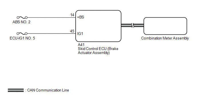
WIRING DIAGRAM
CAUTION / NOTICE / HINT
NOTICE:
- The electric parking brake may still operate up to 20 seconds after the engine switch is turned off. Before disconnecting connectors or fuses, turn the engine switch off and wait 20 seconds or more.
- Inspect the fuses for circuits related to this system before performing the following procedure.
-
After replacing the skid control ECU (brake actuator assembly), perform "Calibration".
Click here
.gif)
- When replacing the skid control ECU (brake actuator assembly), operate the electric parking brake switch assembly as the parking brake indicator light blinks (red) when the engine switch is first turned on (IG).
HINT:
Even if the electric parking brake is operating normally, the parking brake indicator light (red) on the combination meter may be malfunctioning.
PROCEDURE
| 1. | CHECK CAN COMMUNICATION SYSTEM |
(a) Check if CAN communication system DTCs are output.
Chassis > Brake/EPB > Trouble Codes| Result | Proceed to |
|---|---|
| DTCs are not output | A |
| DTCs are output | B |
| B | .gif) | GO TO CAN COMMUNICATION SYSTEM |
|
.gif)
| 2. | VEHICLE OPERATION CHECK |
(a) When the vehicle's tires are lifted off the ground and the Techstream is used to operate the electric parking brake, check the condition of the rear tires.
Click here
| Result | Proceed to |
|---|---|
| Lock and release operation is normal and parking brake indicator light turns off or blinks (red) | A |
| Lock and release operation is malfunctioning and parking brake indicator light illuminates (red) or turns off according to switch operation | B |
| Lock and release operation is malfunctioning and parking brake indicator light turns off or blinks (red) | C |
| B | | INSPECT REAR BRAKE |
| C | | GO TO STEP 4 |
|
| 3. | INSPECT COMBINATION METER ASSEMBLY |
(a) Perform the Active Test of the combination meter assembly using the Techstream.
Body Electrical > Combination Meter > Active Test| Tester Display |
|---|
| Indicat. Park |
(b) Check the combination meter assembly.
OK:
Parking brake indicator light (red) turns on or off in accordance with Techstream operation.
| OK | | REPLACE SKID CONTROL ECU (BRAKE ACTUATOR ASSEMBLY) |
| NG | | GO TO METER / GAUGE SYSTEM |
| 4. | CHECK HARNESS AND CONNECTOR (+BS TERMINAL VOLTAGE) |
(a) Turn the engine switch off.
(b) Disconnect the A41 skid control ECU (brake actuator assembly) connector.
| (c) Measure the voltage according to the value(s) in the table below. Standard Voltage:
|
|
.png)
| NG | | REPAIR OR REPLACE HARNESS OR CONNECTOR |
|
| 5. | CHECK HARNESS AND CONNECTOR (IG1 TERMINAL VOLTAGE) |
(a) Turn the engine switch off.
(b) Disconnect the A41 skid control ECU (brake actuator assembly) connector.
| (c) Measure the voltage according to the value(s) in the table below. Standard Voltage:
|
|
.png)
| OK | | REPLACE SKID CONTROL ECU (BRAKE ACTUATOR ASSEMBLY) |
| NG | | REPAIR OR REPLACE HARNESS OR CONNECTOR |
 Electric Parking Brake Actuator (C13B800)
DESCRIPTION DTC No. Detection Item DTC Detection Condition Trouble Area Memory Note C13B800 Electric Parking Brake Actuator
Diagnosis Condition:
Electric parking brake operatin ...
 Message Not Displayed on Multi-information Display When AUTO Function Set to ON/OFF
DESCRIPTION When the AUTO function is set to ON/OFF, a message is displayed on the multi-information display in the combination meter assembly. WIRING DIAGRAM CAUTION / NOTICE / HINT NOTICE:
The e ...
Other materials:
Lexus RX (RX 350L, RX450h) 2016-2026 Repair Manual > Steering Gear: Reassembly
REASSEMBLY PROCEDURE 1. INSTALL NO. 2 STEERING RACK BOOT (a) Apply lithium soap base glycol grease to the inside of the small opening of a new No. 2 steering rack boot. Lithium Soap Base Glycol Grease (b) Install the No. 2 steering rack boot to the groove on the rack housing. NOTICE:
Be ...
Lexus RX (RX 350L, RX450h) 2016-2026 Repair Manual > Lighting System: Instrument Panel Box Light and Footwell Light Circuit
DESCRIPTION The main body ECU (multiplex network body ECU) controls the instrument panel box light and footwell light. WIRING DIAGRAM CAUTION / NOTICE / HINT NOTICE: Before replacing the main body ECU (multiplex network body ECU), refer to Registration. Click here PROCEDURE 1. PERFORM ACT ...
Lexus RX (RX 350L, RX450h) 2016-{YEAR} Owners Manual
- For your information
- Pictorial index
- For safety and security
- Instrument cluster
- Operation of each component
- Driving
- Lexus Display Audio system
- Interior features
- Maintenance and care
- When trouble arises
- Vehicle specifications
- For owners
Lexus RX (RX 350L, RX450h) 2016-{YEAR} Repair Manual

0.0116