Lexus RX (RX 350L, RX450h) 2016-2025 Repair Manual: Low or High Power Supply Voltage (C1241)
DESCRIPTION
If a malfunction in the power source circuit occurs, or a communication malfunction with the skid control ECU (brake actuator assembly) or speed sensor occurs, the 4WD ECU assembly prohibits operation.
| DTC No. | Detection Item | DTC Detection Condition | Trouble Area |
|---|---|---|---|
| C1241 | Low or High Power Supply Voltage |
|
|
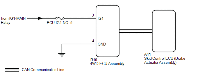
WIRING DIAGRAM
CAUTION / NOTICE / HINT
NOTICE:
- Inspect the fuses for circuits related to this system before performing the following inspection procedure.
-
When the 4WD ECU assembly is replaced with a known good one from another vehicle, it is necessary to perform calibration.
Click here
.gif)
HINT:
Check the condition of each related circuit connector before troubleshooting.
Click here
PROCEDURE
| 1. | CHECK FOR DTC (CAN COMMUNICATION SYSTEM AND VEHICLE STABILITY CONTROL SYSTEM) |
(a) Check if CAN communication DTCs are output.
Click here
(b) Start the engine.
(c) Drive the vehicle, accelerate to a speed of 3 km/h (2 mph) or more for 60 seconds or more, and check if any DTCs related to a speed sensor are output.
Chassis > Brake/EPB > Trouble Codes| Result | Proceed to |
|---|---|
| CAN communication system DTCs and vehicle stability control system DTCs are not output | A |
| CAN communication DTCs are output | B |
| Vehicle stability control system DTCs are output | C |
HINT:
If CAN communication DTCs are output, perform troubleshooting for the CAN communication system first.
| B | .gif) | GO TO CAN COMMUNICATION SYSTEM (HOW TO PROCEED WITH TROUBLESHOOTING) |
| C | | REPAIR CIRCUIT INDICATED BY OUTPUT CODE (VEHICLE STABILITY CONTROL SYSTEM) |
|
.gif)
| 2. | INSPECT BATTERY |
(a) Check the battery voltage.
Standard Voltage:
11 to 14 V
| NG | | CHECK CHARGING SYSTEM |
|
| 3. | CHECK HARNESS AND CONNECTOR (IG1 TERMINAL) |
(a) Disconnect the R10 4WD ECU assembly connector.
(b) Turn the engine switch on (IG).
(c) Measure the voltage according to the value(s) in the table below.
Standard Voltage:
| Tester Connection | Switch Condition | Specified Condition |
|---|---|---|
| R10-3 (IG1) - Body ground | Engine switch on (IG) | 11 to 14 V |
| NG | | REPAIR OR REPLACE HARNESS OR CONNECTOR |
|
| 4. | CHECK HARNESS AND CONNECTOR (GND TERMINAL) |
(a) Turn the engine switch off.
(b) Measure the resistance according to the value(s) in the table below.
Standard Resistance:
| Tester Connection | Condition | Specified Condition |
|---|---|---|
| R10-4 (GND) - Body ground | Always | Below 1 Ω |
| NG | | REPAIR OR REPLACE HARNESS OR CONNECTOR |
|
| 5. | RECONFIRM DTC |
(a) Connect the R10 4WD ECU assembly connector.
(b) Clear the DTCs.
Click here
(c) Start the engine.
(d) Drive the vehicle, accelerate to a speed of 3 km/h (2 mph) or more for 60 seconds or more, and check if the same DTC is output.
Click here
| Result | Proceed to |
|---|---|
| DTCs are output | A |
| DTCs are not output | B |
| A | | REPLACE 4WD ECU ASSEMBLY |
| B | | CHECK FOR INTERMITTENT PROBLEMS |
 Linear Solenoid Power Supply System Malfunction (C120C)
DESCRIPTION This DTC is output by the 4WD ECU assembly if a malfunction occurs in the linear solenoid power supply system. DTC No. Detection Item DTC Detection Condition Trouble Area C120 ...
 Engine Circuit Malfunction (C1280)
DESCRIPTION If a malfunction in the ECM circuit is detected, the 4WD ECU assembly stores this DTC. DTC No. Detection Item DTC Detection Condition Trouble Area C1280 Engine Circuit Malfu ...
Other materials:
Lexus RX (RX 350L, RX450h) 2016-2025 Repair Manual > Smart Access System With Push-button Start (for Start Function): Data List / Active Test
DATA LIST / ACTIVE TEST DATA LIST HINT: Using the Techstream to read the Data List allows the values or states of switches, sensors, actuators and other items to be read without removing any parts. This non-intrusive inspection can be very useful because intermittent conditions or signals may be dis ...
Lexus RX (RX 350L, RX450h) 2016-2025 Repair Manual > Audio And Visual System (for 12.3 Inch Display): Stereo Jack Adapter Light does not Illuminate
DESCRIPTION Power is supplied to the No. 1 stereo jack adapter assembly illumination from the radio receiver assembly. WIRING DIAGRAM CAUTION / NOTICE / HINT NOTICE: Depending on the parts that are replaced during vehicle inspection or maintenance, performing initialization, registration or calibra ...
Lexus RX (RX 350L, RX450h) 2016-{YEAR} Owners Manual
- For your information
- Pictorial index
- For safety and security
- Instrument cluster
- Operation of each component
- Driving
- Lexus Display Audio system
- Interior features
- Maintenance and care
- When trouble arises
- Vehicle specifications
- For owners
Lexus RX (RX 350L, RX450h) 2016-{YEAR} Repair Manual

0.0154