Lexus RX (RX 350L, RX450h) 2016-2026 Repair Manual: AWD Control Switch Circuit
DESCRIPTION
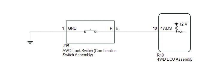
The 4WD ECU assembly changes the control mode in response to the "Lock Mode" signal from the AWD lock switch (combination switch assembly).
WIRING DIAGRAM
CAUTION / NOTICE / HINT
NOTICE:
When the 4WD ECU assembly is replaced with a known good one from another vehicle, it is necessary to perform calibration.
Click here .gif)
HINT:
Check the condition of each related circuit connector before troubleshooting.
Click here
PROCEDURE
| 1. | INSPECT AWD LOCK MODE INDICATOR LIGHT |
(a) Turn the engine switch off.
(b) Connect the Techstream to the DLC3.
(c) Turn the engine switch on (IG).
(d) Turn the Techstream on.
(e) Enter the following menus: Chassis / Four Wheel Drive / Active Test
(f) According to the display on the Techstream, perform the Active Test.
Chassis > Four Wheel Drive > Active Test| Tester Display | Measurement Item | Control Range | Diagnostic Note |
|---|---|---|---|
| 4WD LOCK Light | AWD lock mode indicator light | Indicator light OFF/ON | Observe the combination meter assembly |
(g) When performing the 4WD LOCK Light Active Test, check 4WD LOCK Light in the Data List.
Chassis > Four Wheel Drive > Data List| Tester Display | Measurement Item | Range | Normal Condition | Diagnostic Note |
|---|---|---|---|---|
| 4WD LOCK Light | AWD lock mode indicator light | OFF or ON | OFF: AWD lock mode indicator light off ON: AWD lock mode indicator light on | - |
| Active Test Display |
|---|
| 4WD LOCK Light |
| Data List Display |
|---|
| 4WD LOCK Light |
| Result | Proceed to |
|---|---|
| Data List item 4WD LOCK Light changes according to the Active Test | A |
| Data List item 4WD LOCK Light does not change according to the Active Test | B |
| B | .gif) | REPLACE 4WD ECU ASSEMBLY |
|
.gif)
| 2. | INSPECT COMBINATION SWITCH ASSEMBLY |
(a) Turn the engine switch off.
(b) Remove the AWD lock switch (combination switch assembly).
Click here
(c) Inspect the AWD lock switch (combination switch assembly).
Click here
| NG | | REPLACE COMBINATION SWITCH ASSEMBLY |
|
| 3. | CHECK HARNESS AND CONNECTOR (COMBINATION SWITCH ASSEMBLY - BODY GROUND) |
(a) Measure the resistance according to the value(s) in the table below.
Standard Resistance:
| Tester Connection | Condition | Specified Condition |
|---|---|---|
| J35-1 (GND) - Body ground | Always | Below 1 Ω |
| NG | | REPAIR OR REPLACE HARNESS OR CONNECTOR |
|
| 4. | CHECK HARNESS AND CONNECTOR (COMBINATION SWITCH ASSEMBLY - 4WD ECU ASSEMBLY) |
(a) Reinstall the AWD lock switch (combination switch assembly).
Click here
(b) Disconnect the R10 4WD ECU assembly connector.
(c) Measure the resistance according to the value(s) in the table below.
Standard Resistance:
| Tester Connection | Switch Condition | Specified Condition |
|---|---|---|
| R10-10 (4WDS) - Body ground | Switch pressed and held | Below 100 Ω |
| Switch released | 1 MΩ or higher |
| OK | | REPLACE 4WD ECU ASSEMBLY |
| NG | | REPAIR OR REPLACE HARNESS OR CONNECTOR |
 AWD Warning Light does not Come ON
DESCRIPTION Refer to "AWD Warning Light Remains ON". Click here WIRING DIAGRAM Refer to "AWD Warning Light Remains ON". Click here CAUTION / NOTICE / HINT NOTICE: When the 4WD ECU assembly is repl ...

Other materials:
Lexus RX (RX 350L, RX450h) 2016-2026 Repair Manual > Sfi System: How To Proceed With Troubleshooting
CAUTION / NOTICE / HINT HINT: *: Use the Techstream. PROCEDURE 1. VEHICLE BROUGHT TO WORKSHOP
NEXT 2. CUSTOMER PROBLEM ANALYSIS
NEXT 3. CONNECT TECHSTREAM TO DLC3* HINT: If the display indicates a communication malfunction, inspect the DLC ...
Lexus RX (RX 350L, RX450h) 2016-2026 Repair Manual > Fog Light Assembly: Inspection
INSPECTION PROCEDURE 1. INSPECT FOG LIGHT ASSEMBLY LH (a) Apply battery voltage to the fog light assembly LH and check that the light comes on. OK: Condition Specified Condition Battery positive (+) → Terminal 2 (B) Battery negative (-) → Terminal 3 (E) Fog light comes on If th ...
Lexus RX (RX 350L, RX450h) 2016-{YEAR} Owners Manual
- For your information
- Pictorial index
- For safety and security
- Instrument cluster
- Operation of each component
- Driving
- Lexus Display Audio system
- Interior features
- Maintenance and care
- When trouble arises
- Vehicle specifications
- For owners
Lexus RX (RX 350L, RX450h) 2016-{YEAR} Repair Manual

0.0108