Lexus RX (RX 350L, RX450h) 2016-2026 Repair Manual: Pressure Control Solenoid "D" Actuator Stuck Off (P27137F)
DESCRIPTION
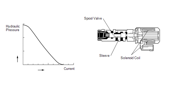
Based on signals from the accelerator position sensor and transmission revolution sensors (NT, NC3 and NC), the ECM controls the shift solenoid valve SLT using a predetermined current. As a result, the line pressure is adjusted to a pressure that is appropriate for the throttle angle and engine output. Based on the rotation speed signals from the transmission revolution sensors (NT, NC3 and NC), the ECM calculates the heat level of the friction material, and detects clutch slippage, etc.
| DTC No. | Detection Item | DTC Detection Condition | Trouble Area | MIL | Memory | Note |
|---|---|---|---|---|---|---|
| P27137F | Pressure Control Solenoid "D" Actuator Stuck Off | 1. Diagnosis Condition 2. Malfunction Status 3. Malfunction Time 4. Other
|
| Comes on | DTC stored | SAE Code: P2714 |
MONITOR DESCRIPTION
The ECM calculates the amount of heat absorbed by the clutch discs and brake discs based on the difference in speed (clutch slippage) between the turbine (input) and output shaft. If the amount of heat absorption exceeds the specified value, the ECM will illuminate the MIL and store this DTC.
If the shift solenoid valve SLT is stuck ON, the line pressure and clutch engagement force will decrease.
NOTICE:
If driving continues under these conditions, the clutches will burn out and the vehicle will no longer be drivable.
MONITOR STRATEGY
| Related DTCs | P2714: Shift solenoid valve SLT/ON malfunction |
| Required sensors/Components | Shift solenoid valve SLT |
| Frequency of operation | Continuous |
| Duration | Immediate |
| MIL operation | 2 driving cycles |
| Sequence of operation | None |
TYPICAL ENABLING CONDITIONS
All| The monitor will run whenever this DTC is not present. (Not circuit malfunction) | P0717, P07BF, P07C0 (Turbine speed sensor circuit) P0793, P07C5, P07C6 (Intermediate shaft speed sensor circuit) P07C1, P07C2, P2767 (Input speed sensor circuit) P0335, P0337, P0338 (Crankshaft Position Sensor "A" circuit) (This condition applies only if using fail-safe) P0712, P0713 (ATF temperature sensor circuit (TFT sensor)) P0748 (Shift solenoid valve SL1 circuit) P0778 (Shift solenoid valve SL2 circuit) P0798 (Shift solenoid valve SL3 circuit) P2810 (Shift solenoid valve SL4 circuit) P2819 (Shift solenoid valve SL5 circuit) P0973, P0974 (Shift solenoid valve S1 circuit) P2716 (Shift solenoid valve SLT circuit) P0115, P0117, P0118 (ECT sensor circuit) P0327, P0328, P032C, P032D, P0332, P0333, P033C, P033D (KCS sensor circuit) P0120, P0121, P0122, P0123, P0220, P0222, P0223, P0604, P0606, P0607, P060A, P060B, P060D, P060E, P0657, P1607, P2102, P2103, P2111, P2112, P2118, P2119, P2135 ((ETCS) Electronic throttle control system) U0100 (CAN communication system) |
| NSW switch | "D" and "not R" and "not N" |
| Duration time from shifting "N" to "D" | 4 sec. or more |
| ATF temperature | -10°C (14°F) or more |
| Engine | Starting |
- Start Conditions of J1summax Calculation
Finish Conditions of J1summax CalculationTurbine speed
270 rpm or more
TCM selected gear
1st
Turbine speed - Output speed x 1st gear ratio
150 rpm or more
Calculated input torque when the first time of following condition met
Specified value
Turbine speed - Output speed x 1st gear ratio
150 rpm or more
Engine speed - Turbine speed
117 rpm or more
Following conditions is met: (a) or (b)
(a) Output speed
More than 0 rpm
(b) Input speed
Less than 60 rpm
Following conditions is met: (a), (b), (c) or (d)
(a) Turbine speed
Less than 270 rpm
(b) TCM selected gear
Not 1st
(c) Duration time while following condition met
0 sec. or more
Turbine speed - Output speed x 1st gear ratio
Less than 50 rpm
(d) Pass condition met
- Start Conditions of J2summax Calculation
Finish Conditions of J2summax CalculationTurbine speed
270 rpm or more
TCM selected gear
2nd
Time after transition to 2nd gear
- when detected abnormal shift
1.5 sec. or more
- when not detected abnormal shift
Immediately after approval
TCM indicated pressure value of SL5
1600 kPa (16.3 kgf/cm2, 232 psi) or more
Turbine speed - Output speed x 2nd gear ratio
150 rpm or more
Calculated input torque when following condition met: (a), (b), (c) and (d)
Specified value
(a) TCM selected gear
2nd
(b) Time after transition to 2nd gear
- when detected abnormal shift
1.5 sec. or more
- when not detected abnormal shift
Immediately after approval
(c) TCM indicate pressure value of SL1
1600 kPa (16.3 kgf/cm2, 232 psi) or more
(d) Turbine speed - Output speed x 2nd gear ratio
150 rpm or more
Following conditions is met: (a), (b), (c) or (d)
(a) Turbine speed
Less than 270 rpm
(b) TCM selected gear
Not 2nd
(c) Duration time while following condition met
0 sec. or more
Turbine speed - Output speed x 2nd gear ratio
Less than 50 rpm
(d) Pass condition met
- Start Conditions of J3summax Calculation
Finish Conditions of J3summax CalculationTurbine speed
270 rpm or more
TCM selected gear
3rd
Time after transition to 3rd gear
- when detected abnormal shift
1.5 sec. or more
- when not detected abnormal shift
Immediately after approval
TCM indicated pressure value of SL1
1600 kPa (16.3 kgf/cm2, 232 psi) or more
Turbine speed - Output speed x 3rd gear ratio
150 rpm or more
Calculated input torque when following condition met: (a), (b), (c) and (d)
Specified value
(a) TCM selected gear
3rd
(b) Time after transition to 3rd gear
- when detected abnormal shift
1.5 sec. or more
- when not detected abnormal shift
Immediately after approval
(c) TCM indicate pressure value of SL1
1600 kPa (16.3 kgf/cm2, 232 psi) or more
(d) Turbine speed - Output speed x 3rd gear ratio
150 rpm or more
Following conditions is met: (a), (b), (c) or (d)
(a) Turbine speed
Less than 270 rpm
(b) TCM selected gear
Not 3rd
(c) Duration time while following condition met
0 sec. or more
Turbine speed - Output speed x 3rd gear ratio
Less than 50 rpm
(d) Pass condition met
- Start Conditions of J4summax Calculation
Finish Conditions of J4summax CalculationTurbine speed
270 rpm or more
TCM selected gear
4th
Time after transition to 4th gear
- when detected abnormal shift
1.5 sec. or more
- when not detected abnormal shift
Immediately after approval
TCM indicated pressure value of SL4
1600 kPa (16.3 kgf/cm2, 232 psi) or more
Turbine speed - Output speed x 4th gear ratio
150 rpm or more
Calculated input torque when following condition met: (a), (b), (c) and (d)
Specified value
(a) TCM selected gear
4th
(b) Time after transition to 4th gear
- when detected abnormal shift
1.5 sec. or more
- when not detected abnormal shift
Immediately after approval
(c) TCM indicate pressure value of SL4
1600 kPa (16.3 kgf/cm2, 232 psi) or more
(d) Turbine speed - Output speed x 4th gear ratio
150 rpm or more
Following conditions is met: (a), (b), (c) or (d)
(a) Turbine speed
Less than 270 rpm
(b) TCM selected gear
Not 4th
(c) Duration time while following condition met
0 sec. or more
Turbine speed - Output speed x 4th gear ratio
Less than 50 rpm
(d) Pass condition met
- Start Conditions of J5summax Calculation
Finish Conditions of J5summax CalculationTurbine speed
270 rpm or more
TCM selected gear
5th
Time after transition to 5th gear
- when detected abnormal shift
1.5 sec. or more
- when not detected abnormal shift
Immediately after approval
TCM indicated pressure value of SL2
1600 kPa (16.3 kgf/cm2, 232 psi) or more
Turbine speed - Output speed x 5th gear ratio
150 rpm or more
Calculated input torque when following condition met: (a), (b), (c) and (d)
Specified value
(a) TCM selected gear
5th
(b) Time after transition to 5th gear
- when detected abnormal shift
1.5 sec. or more
- when not detected abnormal shift
Immediately after approval
(c) TCM indicate pressure value of SL2
1600 kPa (16.3 kgf/cm2, 232 psi) or more
(d) Turbine speed - Output speed x 5th gear ratio
150 rpm or more
Following conditions is met: (a), (b), (c) or (d)
(a) Turbine speed
Less than 270 rpm
(b) TCM selected gear
Not 5th
(c) Duration time while following condition met
0 sec. or more
Turbine speed - Output speed x 5th gear ratio
Less than 50 rpm
(d) Pass condition met
- Start Conditions of J6summax Calculation
Finish Conditions of J6summax CalculationTurbine speed
270 rpm or more
TCM selected gear
6th
Time after transition to 6th gear
- when detected abnormal shift
1.5 sec. or more
- when not detected abnormal shift
Immediately after approval
TCM indicated pressure value of SL4
1600 kPa (16.3 kgf/cm2, 232 psi) or more
Turbine speed - Output speed x 6th gear ratio
150 rpm or more
Calculated input torque when following condition met: (a), (b), (c) and (d)
Specified value
(a) TCM selected gear
6th
(b) Time after transition to 6th gear
- when detected abnormal shift
1.5 sec. or more
- when not detected abnormal shift
Immediately after approval
(c) TCM indicate pressure value of SL4
1600 kPa (16.3 kgf/cm2, 232 psi) or more
(d) Turbine speed - Output speed x 6th gear ratio
150 rpm or more
Following conditions is met: (a), (b), (c) or (d)
(a) Turbine speed
Less than 270 rpm
(b) TCM selected gear
Not 6th
(c) Duration time while following condition met
0 sec. or more
Turbine speed - Output speed x 6th gear ratio
Less than 50 rpm
(d) Pass condition met
- Start Conditions of J7summax Calculation
Finish Conditions of J7summax CalculationTurbine speed
270 rpm or more
TCM selected gear
7th
Time after transition to 7th gear
- when detected abnormal shift
1.5 sec. or more
- when not detected abnormal shift
Immediately after approval
TCM indicated pressure value of SL2
1600 kPa (16.3 kgf/cm2, 232 psi) or more
Turbine speed - Output speed x 7th gear ratio
150 rpm or more
Calculated input torque when following condition met: (a), (b), (c) and (d)
Specified value
(a) TCM selected gear
7th
(b) Time after transition to 7th gear
- when detected abnormal shift
1.5 sec. or more
- when not detected abnormal shift
Immediately after approval
(c) TCM indicate pressure value of SL2
1600 kPa (16.3 kgf/cm2, 232 psi) or more
(d) Turbine speed - Output speed x 7th gear ratio
150 rpm or more
Following conditions is met: (a), (b), (c) or (d)
(a) Turbine speed
Less than 270 rpm
(b) TCM selected gear
Not 7th
(c) Duration time while following condition met
0 sec. or more
Turbine speed - Output speed x 7th gear ratio
Less than 50 rpm
(d) Pass condition met
- Start Conditions of J8summax Calculation
Finish Conditions of J8summax CalculationTurbine speed
270 rpm or more
TCM selected gear
8th
Time after transition to 8th gear
- when detected abnormal shift
1.5 sec. or more
- when not detected abnormal shift
Immediately after approval
TCM indicated pressure value of SL5
1600 kPa (16.3 kgf/cm2, 232 psi) or more
Turbine speed - Output speed x 8th gear ratio
150 rpm or more
Calculated input torque when following condition met: (a), (b), (c) and (d)
Specified value
(a) TCM selected gear
8th
(b) Time after transition to 8th gear
- when detected abnormal shift
1.5 sec. or more
- when not detected abnormal shift
Immediately after approval
(c) TCM indicate pressure value of SL5
1600 kPa (16.3 kgf/cm2, 232 psi) or more
(d) Turbine speed - Output speed x 8th gear ratio
150 rpm or more
Following conditions is met: (a), (b), (c) or (d)
(a) Turbine speed
Less than 270 rpm
(b) TCM selected gear
Not 8th
(c) Duration time while following condition met
0 sec. or more
Turbine speed - Output speed x 8th gear ratio
Less than 50 rpm
(d) Pass condition met
TYPICAL MALFUNCTION THRESHOLDS
When one of the following conditions is met: ON malfunction (A), (B), (C), (D), (E), (F), (G), (H), (I), (J), (K), (L), (M), (N), (O), (P) or (Q)
ON malfunction (A)| Summation of clutch heat generations at 1st gear (J1summax) | Specified value |
| Summation of clutch heat generations at 2nd gear (J2summax) | Specified value |
| Summation of clutch heat generations at 3rd gear (J3summax) | Specified value |
| Summation of clutch heat generations at 4th gear (J4summax) | Specified value |
| Summation of clutch heat generations at 5th gear (J5summax) | Specified value |
| Summation of clutch heat generations at 6th gear (J6summax) | Specified value |
| Summation of clutch heat generations at 7th gear (J7summax) | Specified value |
| Summation of clutch heat generations at 8th gear (J8summax) | Specified value |
| Shift solenoid valve SL1 | OFF malfunction |
| Shift solenoid valve SL1 | ON malfunction |
| Shift solenoid valve SL2 | OFF malfunction |
| Shift solenoid valve SL3 | OFF malfunction |
| Shift solenoid valve SL3 | ON malfunction |
| Shift solenoid valve SL4 | OFF malfunction |
| Shift solenoid valve SL4 | ON malfunction |
| Shift solenoid valve SL5 | OFF malfunction |
| Shift solenoid valve S1 | ON malfunction |
CONFIRMATION DRIVING PATTERN
CAUTION:
When performing the confirmation driving pattern, obey all speed limits and traffic laws.
HINT:
- After repairs have been completed, clear the DTCs and then check that the vehicle has returned to normal by performing the following All Readiness check procedure.
-
When clearing the permanent DTCs, refer to the Clear Permanent DTC procedure.
Click here
.gif)
- Connect the Techstream to the DLC3.
- Turn the engine switch on (IG) and turn the Techstream on.
- Clear the DTCs (even if no DTCs are stored, perform the clear DTC procedure).
- Turn the engine switch off and wait for 2 minutes or more.
- Turn the engine switch on (IG) and turn the Techstream on.
- Start the engine.
-
Perform the D Position Shift Test inspection in Road Test. [*1]
Click here
HINT:
[*1] : Normal judgment procedure.
The normal judgment procedure is used to complete DTC judgment and also used when clearing permanent DTCs.
- Enter the following menus: Powertrain / Transmission / Utility / All Readiness.
- Input the DTC: P27137F.
-
Check the DTC judgment result.
Techstream Display
Description
NORMAL
- DTC judgment completed
- System normal
ABNORMAL
- DTC judgment completed
- System abnormal
INCOMPLETE
- DTC judgment not completed
- Perform driving pattern after confirming DTC enabling conditions
N/A
- Unable to perform DTC judgment
- Number of DTCs which do not fulfill DTC preconditions has reached ECU memory limit
HINT:
- If the judgment result shows NORMAL, the system is normal.
- If the judgment result shows ABNORMAL, the system has a malfunction.
- If the judgment result shows INCOMPLETE or N/A, perform the normal judgment procedure again.
CAUTION / NOTICE / HINT
NOTICE:
-
Perform the universal trip to clear permanent DTCs.
Click here
-
Perform registration and/or initialization when parts related to the automatic transaxle are replaced.
Click here
PROCEDURE
| 1. | CHECK DTC OUTPUT (IN ADDITION TO DTC P27137F) |
(a) Connect the Techstream to the DLC3.
(b) Turn the engine switch on (IG).
(c) Turn the Techstream on.
(d) Enter the following menus: Powertrain / Transmission / Trouble Codes.
Powertrain > Transmission > Trouble Codes(e) Read the DTCs using the Techstream.
| Result | Proceed to |
|---|---|
| DTC P27137F and DTC P07457F, P07507E, P07757F, P07957F, P28077F and/or P28167F are output | A |
| Only DTC P27137F is output | B |
| DTC P07457F, P07507E, P07757F, P07957F, P27137F, P28077F, P28167F and other DTCs are output | C |
HINT:
- If any DTCs other than P07457F, P07507E, P07757F, P07957F, P27137F, P28077F and P28167F are output, perform troubleshooting for those DTCs first.
- If a shift solenoid value is stuck ON or OFF, DTCs for several shift solenoid valves including the malfunctioning shift solenoid valve will be stored.
| B | .gif) | GO TO STEP 5 |
| C | | GO TO DTC CHART |
|
.gif)
| 2. | CLEAR DTC AND PERFORM STALL SPEED TEST |
(a) Clear the DTCs.
Click here
HINT:
Write down the currently output DTCs before clearing them.
Powertrain > Transmission > Clear DTCs(b) Perform the stall speed test.
Click here
| Test Condition | Proceed to |
|---|---|
| Stall speed test can be performed | A |
| Stall speed test cannot be performed | B |
| B | | GO TO STEP 5 |
|
| 3. | INSPECT SHIFT SOLENOID VALVE SL1, SL2, SL3, SL4 AND SL5 |
| (a) Remove the shift solenoid valves SL1, SL2, SL3, SL4 and SL5. Click here |
|
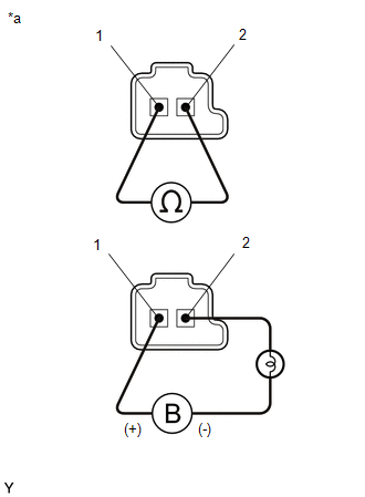
(b) Measure the resistance according to the value(s) in the table below.
Standard Resistance:
| Tester Connection | Condition | Specified Condition |
|---|---|---|
| Shift solenoid valve SL1 connector terminal 1 - terminal 2 | 20°C (68°F) | 5.0 to 5.6 Ω |
| Shift solenoid valve SL2 connector terminal 1 - terminal 2 | 20°C (68°F) | 5.0 to 5.6 Ω |
| Shift solenoid valve SL3 connector terminal 1 - terminal 2 | 20°C (68°F) | 5.0 to 5.6 Ω |
| Shift solenoid valve SL4 connector terminal 1 - terminal 2 | 20°C (68°F) | 5.0 to 5.6 Ω |
| Shift solenoid valve SL5 connector terminal 1 - terminal 2 | 20°C (68°F) | 5.0 to 5.6 Ω |
(c) Connect a positive (+) lead from the battery to terminal 1 and a negative (-) lead with a 21 W bulb to terminal 2 of the solenoid valve connector. Check that the valve moves and makes an operating sound.
OK:
Valve moves and makes an operating sound.
| NG | | REPLACE SHIFT SOLENOID VALVE SL1, SL2, SL3, SL4 OR SL5 |
|
| 4. | INSPECT SHIFT SOLENOID VALVE S1 |
| (a) Remove the shift solenoid valve S1. Click here |
|
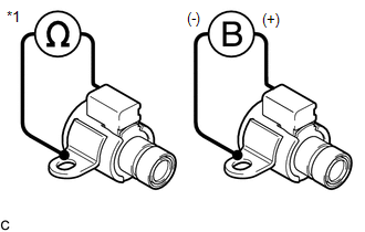
(b) Measure the resistance according to the value(s) in the table below.
Standard Resistance:
| Tester Connection | Condition | Specified Condition |
|---|---|---|
| Shift solenoid valve S1 connector terminal - Shift solenoid valve S1 body | 20°C (68°F) | 11 to 15 Ω |
(c) Connect a positive (+) lead from the battery to the terminal of the solenoid valve connector, and a negative (-) lead to the solenoid body. Check that the valve moves and makes an operating sound.
OK:
Valve moves and makes an operating sound.
| NG | | REPLACE SHIFT SOLENOID VALVE S1 |
|
| 5. | INSPECT SHIFT SOLENOID VALVE SLT |
| (a) Remove the shift solenoid valve SLT. Click here |
|
(b) Measure the resistance according to the value(s) in the table below.
Standard Resistance:
| Tester Connection | Condition | Specified Condition |
|---|---|---|
| Shift solenoid valve SLT connector terminal 1 - terminal 2 | 20°C (68°F) | 5.0 to 5.6 Ω |
(c) Connect a positive (+) lead from the battery to terminal 1 and a negative (-) lead with a 21 W bulb to terminal 2 of the solenoid valve connector. Check that the valve moves and makes an operating sound.
OK:
Valve moves and makes an operating sound.
| NG | | REPLACE SHIFT SOLENOID VALVE SLT |
|
| 6. | INSPECT TRANSMISSION VALVE BODY ASSEMBLY |
(a) Inspect the transmission valve body assembly.
Click here
OK:
There is no foreign matter on each valve and they operate smoothly.
| NG | | REPAIR OR REPLACE TRANSMISSION VALVE BODY ASSEMBLY |
|
| 7. | INSPECT TORQUE CONVERTER ASSEMBLY |
(a) Inspect the torque converter assembly.
Click here
OK:
The torque converter assembly is normal.
| NG | | REPAIR OR REPLACE TORQUE CONVERTER ASSEMBLY |
|
| 8. | REPAIR OR REPLACE AUTOMATIC TRANSAXLE ASSEMBLY |
(a) Repair or replace the automatic transaxle assembly.
Click here
| NEXT | | PERFORM A/T CODE REGISTRATION |
 Pressure Control Solenoid "D" Circuit Open (P271313)
DESCRIPTION Refer to DTC P27137F. Click here DTC No. Detection Item DTC Detection Condition Trouble Area MIL Memory Note P271313 Pressure Control Solenoid "D" Circuit Open 1 ...
 Torque Converter Clutch Pressure Control Solenoid Control Circuit Open (P275613)
DESCRIPTION The ECM controls the shift solenoid valve SLU using a predetermined current, and performs lock-up and flex lock-up control. DTC No. Detection Item DTC Detection Condition Trouble ...
Other materials:
Lexus RX (RX 350L, RX450h) 2016-2026 Repair Manual > Power Mirror Control System (w/o Memory): Data List / Active Test
DATA LIST / ACTIVE TEST DATA LIST HINT: Using the Techstream to read the Data List allows the values or states of switches, sensors, actuators and other items to be read without removing any parts. This non-intrusive inspection can be very useful because intermittent conditions or signals may be dis ...
Lexus RX (RX 350L, RX450h) 2016-2026 Repair Manual > Audio And Visual System (for 12.3 Inch Display): Pointer not Displayed on Screen or Pointer does not Move
CAUTION / NOTICE / HINT NOTICE: Depending on the parts that are replaced during vehicle inspection or maintenance, performing initialization, registration or calibration may be needed. Refer to Precaution for Audio and Visual System. Click here PROCEDURE 1. CHECK FOR FOREIGN MATTER (a) Ch ...
Lexus RX (RX 350L, RX450h) 2016-{YEAR} Owners Manual
- For your information
- Pictorial index
- For safety and security
- Instrument cluster
- Operation of each component
- Driving
- Lexus Display Audio system
- Interior features
- Maintenance and care
- When trouble arises
- Vehicle specifications
- For owners
Lexus RX (RX 350L, RX450h) 2016-{YEAR} Repair Manual

0.0119