Lexus RX (RX 350L, RX450h) 2016-2026 Repair Manual: Fuel Rail Pressure Sensor "A" Circuit Short to Ground (P019011)
DESCRIPTION
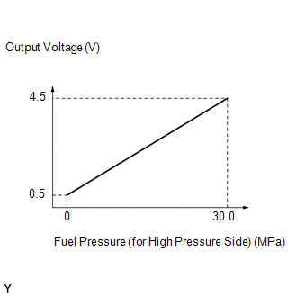
The fuel pressure sensor (for high pressure side) is installed on the fuel delivery pipe (for high pressure side). The fuel pressure sensor (for high pressure side) changes the fuel pressure for high pressure side into an electrical signal and sends the signal to the ECM. Then the ECM controls the pump discharge using this feedback to maintain the fuel's target pressure between 2 and 25 MPa (20 and 255 kgf/cm2).
| DTC No. | Detection Item | DTC Detection Condition | Trouble Area | MIL | Memory | Note |
|---|---|---|---|---|---|---|
| P019011 | Fuel Rail Pressure Sensor "A" Circuit Short to Ground | The fuel pressure sensor (for high pressure side) output voltage is less than 0.2933 V for 3 seconds or more (1 trip detection logic). |
| Comes on | DTC stored | SAE Code: P0192 |
HINT:
When this DTC is output, check the fuel pressure (for high pressure side) in the Data List. Enter the following menus: Powertrain / Engine / Data List / Fuel Pressure (High).
| DTC No. | Fuel Pressure (High) | Malfunction |
|---|---|---|
| P019011 | Approximately 0 kPag |
|
If the Data List values is normal it may be due to a temporary recovery from the malfunction condition. Check for intermittent problems.
MONITOR DESCRIPTION
This DTC is stored if the fuel pressure sensor (for high pressure side) output voltage is out of the standard range due to an open or short in the sensor circuit.
Example:
If the fuel pressure sensor (for high pressure side) output voltage is less than 0.2933 V for 3 seconds or more, the ECM store this DTC.
MONITOR STRATEGY
| Related DTCs | P0192: Fuel rail pressure sensor range check (Low voltage) |
| Required Sensors/Components (Main) | Fuel pressure sensor (for high pressure side) |
| Required Sensors/Components (Related) | - |
| Frequency of Operation | Continuous |
| Duration | 3 seconds |
| MIL Operation | Immediate |
| Sequence of Operation | None |
TYPICAL ENABLING CONDITIONS
| Monitor runs whenever the following DTCs are not stored | None |
| All of the following conditions are met | - |
| Battery voltage | 8 V or higher |
| Engine switch | On (IG) |
| Starter | Off |
| Time after engine start | 5 seconds or more |
TYPICAL MALFUNCTION THRESHOLDS
| Fuel rail pressure sensor voltage | Less than 0.2933 V |
CONFIRMATION DRIVING PATTERN
HINT:
-
After repair has been completed, clear the DTC and then check that the vehicle has returned to normal by performing the following All Readiness check procedure.
Click here
.gif)
-
When clearing the permanent DTCs, refer to the "CLEAR PERMANENT DTC" procedure.
Click here
- Connect the Techstream to the DLC3.
- Turn the engine switch on (IG).
- Turn the Techstream on.
- Clear the DTCs (even if no DTCs are stored, perform the clear DTC procedure).
- Turn the engine switch off and wait for at least 30 seconds.
- Start the engine [A].
- Idle the engine for 10 seconds [B].
- Turn the Techstream on
- Enter the following menus: Powertrain / Engine / Trouble Codes [C].
-
Read the pending DTCs.
HINT:
- If a pending DTC is output, the system is malfunctioning.
- If a pending DTC is not output, perform the following procedure.
- Enter the following menus: Powertrain / Engine / Utility / All Readiness.
- Input the DTC: P019011.
-
Check the DTC judgment result.
Techstream Display
Description
NORMAL
- DTC judgment completed
- System normal
ABNORMAL
- DTC judgment completed
- System abnormal
INCOMPLETE
- DTC judgment not completed
- Perform driving pattern after confirming DTC enabling conditions
HINT:
- If the judgment result shows NORMAL, the system is normal.
- If the judgment result shows ABNORMAL, the system has a malfunction.
- If the judgment result shows INCOMPLETE, perform steps [B] through [C] again.
-
[A] to [C]: Normal judgment procedure.
The normal judgment procedure is used to complete DTC judgment and also used when clearing permanent DTCs.
- When clearing the permanent DTCs, do not disconnect the cable from the battery terminal or attempt to clear the DTCs during this procedure, as doing so will clear the universal trip and normal judgment histories.
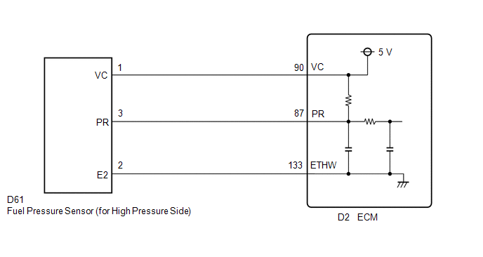
WIRING DIAGRAM
CAUTION / NOTICE / HINT
HINT:
Read freeze frame data using the Techstream. The ECM records vehicle and driving condition information as freeze frame data the moment a DTC is stored. When troubleshooting, freeze frame data can help determine if the vehicle was moving or stationary, if the engine was warmed up or not, if the air fuel ratio was lean or rich, and other data from the time the malfunction occurred.
PROCEDURE
| 1. | CHECK HARNESS AND CONNECTOR (FUEL PRESSURE SENSOR (FOR HIGH PRESSURE SIDE) - ECM) |
(a) Disconnect the fuel pressure sensor (for high pressure side) connector.
(b) Disconnect the ECM connector.
(c) Measure the resistance according to the value(s) in the table below.
Standard Resistance:
| Tester Connection | Condition | Specified Condition |
|---|---|---|
| D61-1 (VC) - D2-90 (VC) | Always | Below 1 Ω |
| D61-3 (PR) or D2-87 (PR) - Body ground and other terminals | Always | 10 kΩ or higher |
| NG | .gif) | REPAIR OR REPLACE HARNESS OR CONNECTOR |
|
.gif)
| 2. | CHECK TERMINAL VOLTAGE (POWER SOURCE OF FUEL PRESSURE SENSOR (FOR HIGH PRESSURE SIDE)) |
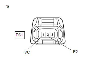
| *a | Front view of wire harness connector (to Fuel Pressure Sensor (for High Pressure Side)) |
(a) Disconnect the fuel pressure sensor (for high pressure side) connector.
(b) Turn the engine switch on (IG).
(c) Measure the voltage according to the value(s) in the table below.
Standard Voltage:
| Tester Connection | Condition | Specified Condition |
|---|---|---|
| D61-1 (VC) - D61-2 (E2) | Engine switch on (IG) | 4.75 to 5.25 V |
HINT:
Perform "Inspection After Repair" after replacing the fuel pressure sensor (for high pressure side).
Click here
| OK | | REPLACE FUEL DELIVERY PIPE WITH SENSOR ASSEMBLY LH (FUEL PRESSURE SENSOR (FOR HIGH PRESSURE SIDE)) |
| NG | | REPLACE ECM |
 System Too Lean Bank 1 (P017100,P017200,P017400,P017500,P117000,P117B00)
DESCRIPTION The fuel trim is related to the feedback compensation value, not to the basic injection duration. The fuel trim consists of both the short-term and long-term fuel trims. The short-term fue ...
 Fuel Rail Pressure Sensor "A" Circuit Short to Battery or Open (P019015)
DESCRIPTION Refer to DTC P019011. Click here DTC No. Detection Item DTC Detection Condition Trouble Area MIL Memory Note P019015 Fuel Rail Pressure Sensor "A" Circuit Short to B ...
Other materials:
Lexus RX (RX 350L, RX450h) 2016-2026 Repair Manual > Dynamic Radar Cruise Control System: Definition Of Terms
DEFINITION OF TERMS Term Definition Monitor description Description of what the ECM monitors and how it detects malfunctions (monitoring purpose and details). Related DTCs Group of diagnostic trouble codes that are output by the ECM based on the same malfunction detection logic. ...
Lexus RX (RX 350L, RX450h) 2016-2026 Repair Manual > Smart Access System With Push-button Start (for Entry Function): Open in Front Passenger Side Electrical Antenna Circuit (B27A2)
DESCRIPTION The certification ECU (smart key ECU assembly) generates a request signal and transmits the signal to the front door outside handle assembly (for front passenger door) (electrical key antenna) at intervals of 0.25 seconds. For the front door outside handle assembly (for front passenger d ...
Lexus RX (RX 350L, RX450h) 2016-{YEAR} Owners Manual
- For your information
- Pictorial index
- For safety and security
- Instrument cluster
- Operation of each component
- Driving
- Lexus Display Audio system
- Interior features
- Maintenance and care
- When trouble arises
- Vehicle specifications
- For owners
Lexus RX (RX 350L, RX450h) 2016-{YEAR} Repair Manual

0.0121