Lexus RX (RX 350L, RX450h) 2016-2026 Repair Manual: Reassembly
REASSEMBLY
PROCEDURE
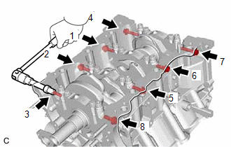
1. INSTALL NO. 1 OIL NOZZLE SUB-ASSEMBLY
| (a) Using a 5 mm hexagon socket wrench, install the 3 No. 1 oil nozzle sub-assemblies to the cylinder block sub-assembly with the 3 bolts. Torque: 9.0 N·m {92 kgf·cm, 80 in·lbf} |
|
.png)
2. INSTALL PISTON
HINT:
Perform this procedure only when replacement of the piston pin hole snap ring (rear side) is necessary.
(a) Using a screwdriver, install a new piston pin hole snap ring (rear side) at one end of the piston pin hole.
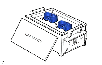
| (b) Gradually heat the piston to approximately 80°C (176°F). |
|
(c) Coat the piston pin with engine oil.
CAUTION:
Be sure to wear protective gloves.
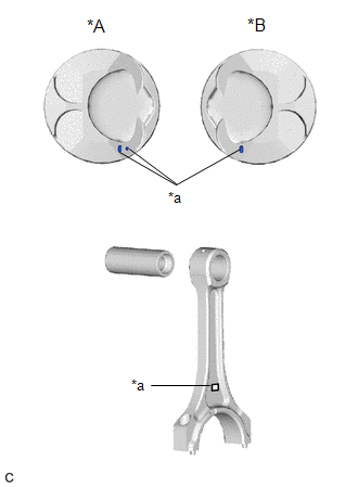
| (d) Align the front marks of the piston and connecting rod sub-assembly, and push in the piston pin with your thumb. HINT: The piston and piston pin are a matched set. |
|
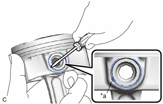
| (e) Using a screwdriver, install a new piston pin hole snap ring at the other end of the piston pin hole. NOTICE: Make sure that the end gap of the snap ring is not aligned with the cutout of the piston pin hole. |
|
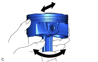
| (f) Check the fitting condition between the piston and piston pin. (1) Move the connecting rod back and forth on the piston pin. Check the fitting condition. HINT: If abnormal movement is felt, replace the piston and piston pin as a set. (2) Rotate the piston back and forth on the piston pin. Check the fitting condition. HINT:
|
|
3. INSTALL PISTON RING SET
(a) Install the oil ring expander and 2 side rails by hand.
| (b) Using a piston ring expander, install the No. 1 compression ring and No. 2 compression ring as shown in the illustration. NOTICE:
|
|
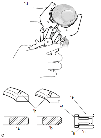
| (c) Position the piston ring set so that the ring ends are as shown in the illustration. NOTICE: Do not align the ring ends. HINT: Perform Inspection After Repair after replacing the piston ring. Click here |
|
4. INSTALL CRANKSHAFT BEARING
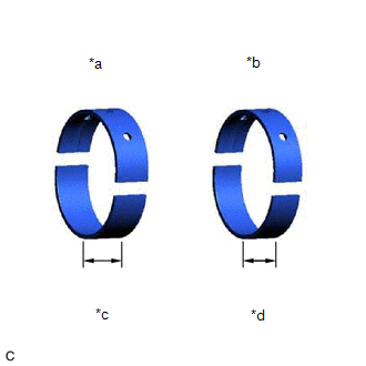
| (a) Clean the main journals and both surfaces of the crankshaft bearings. NOTICE: Crankshaft bearings come in widths of 17.9 mm (0.705 in.) and 20.9 mm (0.823 in.). Install the 20.9 mm (0.823 in.) crankshaft bearings to the No. 1 and No. 4 cylinder block journal positions. Install the 17.9 mm (0.705 in.) crankshaft bearings to the No. 2 and No. 3 positions. |
|
| (b) Install the upper crankshaft bearing. (1) Install the upper crankshaft bearings to the cylinder block sub-assembly as shown in the illustration. NOTICE:
|
|
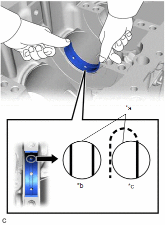
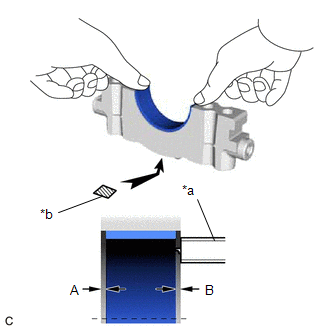
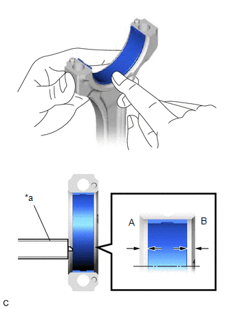
| (c) Install the lower crankshaft bearing. (1) Install the lower crankshaft bearings to the crankshaft bearing caps. (2) Using a vernier caliper, measure the distance between the crankshaft bearing cap edge and lower crankshaft bearing edge. Difference Between (A) and (B): 0.7 mm (0.0276 in.) or less NOTICE:
|
|
5. INSTALL CRANKSHAFT THRUST WASHER SET
(a) Apply engine oil to the crankshaft thrust washer set.
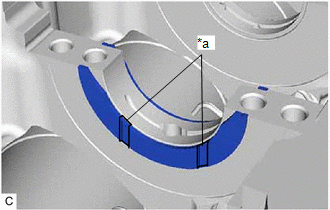
| (b) Install the crankshaft thrust washer set under the No. 2 journal position of the cylinder block sub-assembly with the oil grooves facing outward. |
|
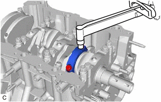
6. INSTALL CRANKSHAFT
(a) Apply engine oil to the crankshaft bearings, then place the crankshaft on the cylinder block sub-assembly.
| (b) Confirm the projections and numbers of the crankshaft bearing caps and install the 4 crankshaft bearing caps to the cylinder block sub-assembly. HINT: A number is marked on each crankshaft bearing cap to indicate its installation position. |
|
(c) Apply a light coat of engine oil to the threads and under the heads of the crankshaft bearing cap set bolts.
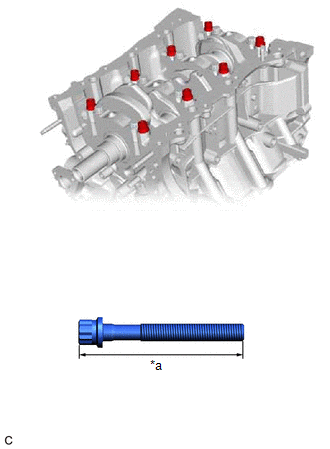
| (d) Temporarily install the 8 crankshaft bearing cap set bolts to the inside positions. Bolt Length: 100 to 102 mm (3.94 to 4.02 in.) |
|
(e) Push the crankshaft bearing cap with your hand until the clearance between the crankshaft bearing cap and the cylinder block sub-assembly is less than 6 mm (0.236 in.) by using the 2 inside crankshaft bearing cap set bolts as a guide.
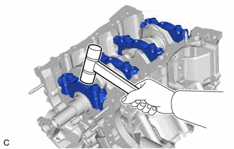
| (f) Using a plastic hammer, lightly tap the crankshaft bearing cap to ensure a proper fit. |
|
(g) Apply a light coat of engine oil to the threads and under the heads of the 8 crankshaft bearing cap set bolts.
| (h) Temporarily install the 8 crankshaft bearing cap set bolts to the outside positions. Bolt Length: 105.5 to 107.5 mm (4.15 to 4.23 in.) |
|
(i) Install the crankshaft bearing cap set bolts.
HINT:
The crankshaft bearing cap set bolts are tightened in 2 progressive steps.
(j) Step 1:
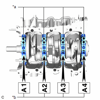
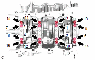
| (1) Uniformly tighten the 16 crankshaft bearing cap set bolts in several steps in the order shown in the illustration. Torque: 61 N·m {622 kgf·cm, 45 ft·lbf} HINT: If a crankshaft bearing cap bolt cannot be tightened to the specified torque, replace it. |
|
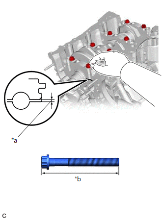
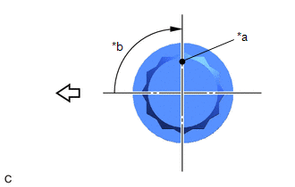
(k) Step 2:
(1) Mark the front of the crankshaft bearing cap set bolts with paint.
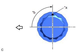
| *a | Paint Mark |
| *b | Turn 90° |
.png) | Front of Engine |
(2) Tighten the crankshaft bearing cap set bolts 90° in the order shown in the illustration.
(3) Check that the paint marks are now at a 90° angle to the front.
| (l) Install 8 new seal washers and uniformly tighten the 8 crankshaft bearing cap set bolts in several steps in the order shown in the illustration. Torque: 51.5 N·m {525 kgf·cm, 38 ft·lbf} |
|
(m) Check that the crankshaft turns smoothly.
(n) Check the crankshaft thrust clearance.
Click here .gif)
7. INSTALL CONNECTING ROD BEARING
(a) Install the connecting rod bearings to the connecting rod sub-assembly and connecting rod cap.
| (b) Using a vernier caliper, measure the distance between the connecting rod sub-assembly and connecting rod cap edges and the connecting rod bearing edge. Difference Between (A) and (B): 0.7 mm (0.0276 in.) or less NOTICE: Do not apply engine oil to the connecting rod bearings or the contact surfaces. |
|
8. INSTALL PISTON SUB-ASSEMBLY WITH CONNECTING ROD
(a) Apply engine oil to the cylinder walls, the pistons, and the surfaces of the connecting rod bearings.
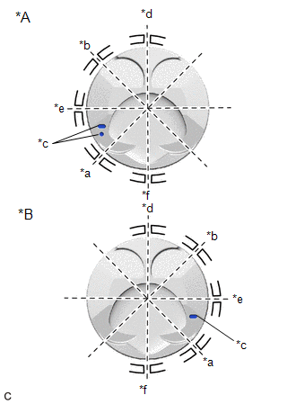
| (b) Position the piston rings so that the ring ends are as shown in the illustration. NOTICE: Do not align the ring ends. |
|
(c) Using a piston ring compressor, push the piston and connecting rod sub-assembly into the cylinder with the front mark of the piston facing the front of the engine.
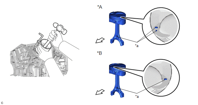
| *A | for Bank 1 | *B | for Bank 2 |
| *a | Front Mark | | Front of Engine |
NOTICE:
Match the connecting rod cap with the connecting rod sub-assembly.
(d) Check that the front mark of the connecting rod cap is facing the front of the engine.
| *a | Front Mark |
| | Front of Engine |
(e) Apply a light coat of engine oil to the threads and under the heads of the connecting rod cap bolts.
(f) Install the 2 connecting rod cap bolts.
HINT:
The connecting rod cap bolts are tightened in 2 progressive steps.
(g) Step 1:
| (1) Alternately tighten the 2 connecting rod cap bolts in several steps. Torque: 24.5 N·m {250 kgf·cm, 18 ft·lbf} |
|
(h) Step 2:
| *a | Paint Mark |
| *b | Turn 90° |
| | Front of Engine |
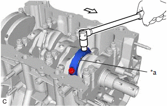
(1) Mark the front of each connecting rod cap bolt with paint.
(2) Further tighten the connecting rod cap bolts 90° as shown in the illustration.
(3) Check that the paint marks are now at a 90° angle to the front.
(i) Confirm that the crankshaft turns smoothly.
(j) Check the connecting rod thrust clearance.
Click here
9. INSTALL CYLINDER BLOCK WATER JACKET SPACER
| (a) Install the cylinder block water jacket spacer and cylinder block water jacket spacer LH to the cylinder block sub-assembly. NOTICE: Firmly press the water jacket spacer into the cylinder block sub-assembly and confirm that it is not protruding from the surface. |
|
.png)
 Inspection
INSPECTION PROCEDURE 1. INSPECT CONNECTING ROD THRUST CLEARANCE (a) Install the connecting rod cap. Click here (b) Using a dial indicator, measure the thrust clearance while moving the connecting ...
 Cylinder Head
...
Other materials:
Lexus RX (RX 350L, RX450h) 2016-2026 Repair Manual > Network Gateway Ecu: Installation
INSTALLATION CAUTION / NOTICE / HINT PROCEDURE 1. INSTALL NETWORK GATEWAY ECU (a) Engage the 2 claws to install the network gateway ECU. 2. INSTALL ECU INTEGRATION BOX RH Click here 3. CONNECT CABLE TO NEGATIVE BATTERY TERMINAL NOTICE: When disconnecting the cable, some systems need to be initial ...
Lexus RX (RX 350L, RX450h) 2016-2026 Repair Manual > Lighting System: System Description
SYSTEM DESCRIPTION ILLUMINATED ENTRY SYSTEM (a) The illuminated entry system has the following control functions: Control Outline Lights that Operate Actuation Area-linked When a registered key is brought within any vehicle exterior detection area around the doors, the items listed to t ...
Lexus RX (RX 350L, RX450h) 2016-{YEAR} Owners Manual
- For your information
- Pictorial index
- For safety and security
- Instrument cluster
- Operation of each component
- Driving
- Lexus Display Audio system
- Interior features
- Maintenance and care
- When trouble arises
- Vehicle specifications
- For owners
Lexus RX (RX 350L, RX450h) 2016-{YEAR} Repair Manual

0.015