Lexus RX (RX 350L, RX450h) 2016-2026 Repair Manual: Removal
REMOVAL
CAUTION / NOTICE / HINT
The necessary procedures (adjustment, calibration, initialization or registration) that must be performed after parts are removed and installed, or replaced during fuel pump assembly removal/installation are shown below.
Necessary Procedures After Parts Removed/Installed/Replaced| Replaced Part or Performed Procedure | Necessary Procedure | Effect/Inoperative Function when Necessary Procedure not Performed | Link |
|---|---|---|---|
|
*1: When performing learning using the Techstream.
Click here | |||
| Battery terminal is disconnected/reconnected | Memorize steering angle neutral point | Lane Control System | |
| Pre-collision system | |||
| Intelligent clearance sonar system*1 | |||
| Lighting system (w/ Automatic Headlight Beam Level Control System) | | ||
| Parking assist monitor system | | ||
| Panoramic view monitor system | | ||
| Initialize back door lock | Power door lock control system | | |
| Reset back door close position | Power Back Door System (w/ Outside Door Control Switch) | | |
| Inspection After Repair |
| |
PROCEDURE
1. PRECAUTION
NOTICE:
After turning the engine switch off, waiting time may be required before disconnecting the cable from the negative (-) battery terminal. Therefore, make sure to read the disconnecting the cable from the negative (-) battery terminal notices before proceeding with work.
Click here .gif)
2. DISCHARGE FUEL SYSTEM PRESSURE
Click here
3. DISCONNECT CABLE FROM NEGATIVE BATTERY TERMINAL
NOTICE:
When disconnecting the cable, some systems need to be initialized after the cable is reconnected.
Click here
4. REMOVE INTAKE MANIFOLD
Click here
5. REMOVE NO. 2 ENGINE UNDER COVER
Click here
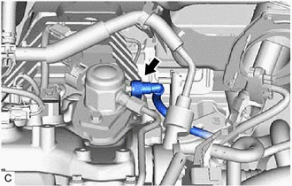
6. REMOVE FUEL PUMP PROTECTOR
| (a) Disengage the clamp to disconnect the fuel tube sub-assembly from the fuel pump protector. |
|
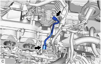
| (b) Remove the 2 bolts and fuel pump protector from the cylinder head sub-assembly. |
|
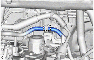
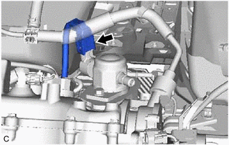
7. DISCONNECT NO. 2 FUEL TUBE SUB-ASSEMBLY
| (a) Disconnect the No. 2 fuel tube sub-assembly from the fuel pump assembly. Click here |
|
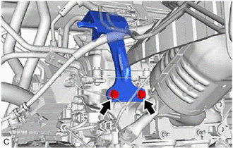
8. REMOVE NO. 1 FUEL PIPE SUB-ASSEMBLY
.png)
CAUTION:
To prevent serious injury due to fuel spray from the high-pressure fuel lines, always discharge fuel system pressure before removing any fuel system components.
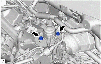
| (a) Using a 17 mm union nut wrench, loosen the 2 union nuts of the No. 1 fuel pipe sub-assembly. |
|
| (b) Loosen the 2 bolts of the fuel pump assembly. |
|
(c) Remove the No. 1 fuel pipe sub-assembly from the fuel delivery pipe RH and fuel pump assembly.
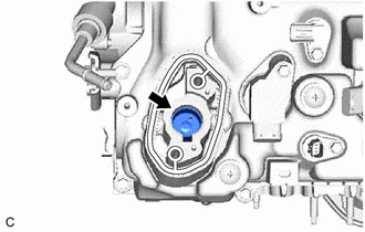
9. REMOVE FUEL PUMP ASSEMBLY
| (a) Disconnect the fuel pump assembly connector. |
|
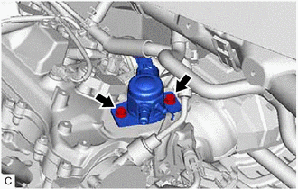
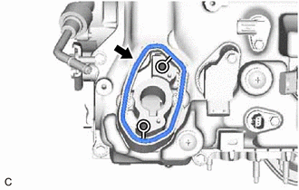
| (b) Remove the 2 bolts, fuel pump assembly and fuel pump lifter guide from the cylinder head cover sub-assembly. |
|
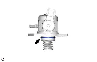
| (c) Remove the O-ring from the fuel pump assembly. |
|
| (d) Remove the fuel pump lifter assembly from the fuel pump lifter housing. |
|
| (e) Remove the fuel pump spacer gasket from the cylinder head cover sub-assembly. |
|
 On-vehicle Inspection
ON-VEHICLE INSPECTION PROCEDURE 1. FUEL PUMP ASSEMBLY OPERATION (a) Check fuel pressure. (1) Connect the Techstream to the DLC3. (2) Start the engine. (3) Turn the Techstream on. (4) Enter the followi ...
 Inspection
INSPECTION PROCEDURE 1. INSPECT FUEL PUMP ASSEMBLY (a) Measure the resistance according to the value(s) in the table below. Standard Resistance: Tester Connection Condition Specified Condit ...
Other materials:
Lexus RX (RX 350L, RX450h) 2016-2026 Repair Manual > Lighting System: System Diagram
SYSTEM DIAGRAM ...
Lexus RX (RX 350L, RX450h) 2016-2026 Repair Manual > Immobiliser System: Terminals Of Ecu
TERMINALS OF ECU CHECK ENGINE SWITCH (a) Measure the voltage and resistance according to the value(s) in the table below. Terminal No. (Symbol) Input/Output Wiring Color Terminal Description Condition Specified Condition Related Data List Item/DTC J14-6 (AGND) - Body ground - ...
Lexus RX (RX 350L, RX450h) 2016-{YEAR} Owners Manual
- For your information
- Pictorial index
- For safety and security
- Instrument cluster
- Operation of each component
- Driving
- Lexus Display Audio system
- Interior features
- Maintenance and care
- When trouble arises
- Vehicle specifications
- For owners
Lexus RX (RX 350L, RX450h) 2016-{YEAR} Repair Manual

0.0102