Lexus RX (RX 350L, RX450h) 2016-2026 Repair Manual: Installation
INSTALLATION
PROCEDURE
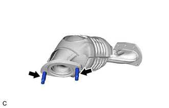
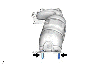
1. INSTALL STUD BOLT
HINT:
If a stud bolt is deformed or its threads are damaged, replace it.
| (a) Using an E8 "TORX" socket wrench, install the 2 stud bolts to the exhaust manifold (TWC: Front Catalyst). Torque: 19.5 N·m {199 kgf·cm, 14 ft·lbf} |
|
| (b) Using an E8 "TORX" socket wrench, install the 2 stud bolts to the exhaust manifold assembly LH (TWC: Front Catalyst). Torque: 19.5 N·m {199 kgf·cm, 14 ft·lbf} |
|
2. INSTALL EXHAUST MANIFOLD TO HEAD GASKET (for Bank 2)
(a) Install a new exhaust manifold to head gasket to the cylinder head sub-assembly.
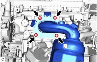
3. INSTALL EXHAUST MANIFOLD ASSEMBLY LH (TWC: Front Catalyst)
(a) Temporarily install the exhaust manifold assembly LH (TWC: Front Catalyst) with the 4 nuts.
(b) Temporarily install the No. 2 manifold stay to the exhaust manifold assembly LH (TWC: Front Catalyst) and cylinder block sub-assembly with the bolt and nut.
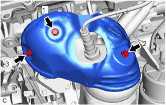
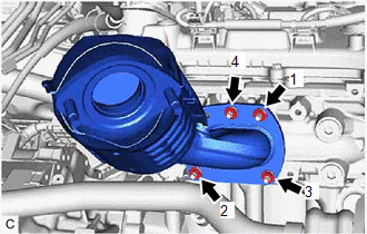
| (c) Using a 12 mm deep socket wrench, tighten the 4 nuts in the order shown in the illustration. Torque: 21 N·m {214 kgf·cm, 15 ft·lbf} |
|
(d) Tighten the bolt and nut in the order shown in the illustration.
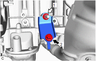
.png) | Bolt |
.png) | Nut |
Torque:
34 N·m {347 kgf·cm, 25 ft·lbf}
(e) Connect the No. 1 radiator hose to the radiator assembly and slide the clip to secure it.
(f) Connect the 2 No. 2 cooling fan motor connectors.
4. INSTALL AIR FUEL RATIO SENSOR (for Bank 2)
Click here .gif)
5. INSTALL NO. 2 EXHAUST MANIFOLD HEAT INSULATOR
| (a) Install the No. 2 exhaust manifold heat insulator to the exhaust manifold assembly LH (TWC: Front Catalyst) with the 3 bolts in the order shown in the illustration. Torque: 8.5 N·m {87 kgf·cm, 75 in·lbf} |
|
(b) Engage the wire harness clamp.
(c) Connect the air fuel ratio sensor connector.
6. INSTALL V-BANK COVER SUB-ASSEMBLY
Click here
7. INSTALL ENGINE OIL LEVEL DIPSTICK GUIDE
Click here
8. INSTALL FRONT EXHAUST PIPE ASSEMBLY
Click here
9. INSTALL NO. 1 EXHAUST PIPE SUPPORT BRACKET (for Lower Side)
Click here
10. INSTALL EXHAUST MANIFOLD TO HEAD GASKET (for Bank 1)
(a) Install a new exhaust manifold to head gasket to the cylinder head sub-assembly RH.
11. INSTALL EXHAUST MANIFOLD (TWC: Front Catalyst)
(a) Temporarily install the exhaust manifold (TWC: Front Catalyst) with the 4 nuts.
(b) Temporarily install the manifold stay to the exhaust manifold (TWC: Front Catalyst) and rear engine mounting bracket with the bolt and nut.
| (c) Using a 12 mm deep socket wrench, tighten the 4 nuts in the order shown in the illustration. Torque: 21 N·m {214 kgf·cm, 15 ft·lbf} |
|
(d) Tighten the bolt and nut in the order shown in the illustration.
Torque:
34 N·m {347 kgf·cm, 25 ft·lbf}
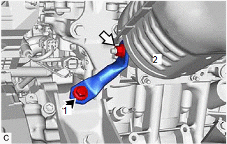
| | Bolt |
| | Nut |
12. INSTALL FRONT NO. 3 EXHAUST PIPE SUB-ASSEMBLY
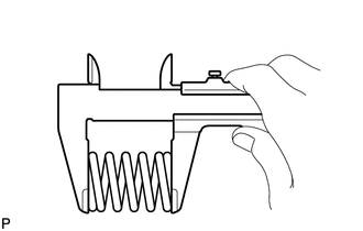
| (a) Using a vernier caliper, measure the free length of the 2 compression springs.
If the free length is less than minimum, replace the compression spring. |
|
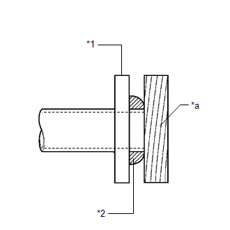
(b) Temporarily install a new exhaust pipe gasket to the front No. 3 exhaust pipe sub-assembly (center exhaust pipe assembly (TWC: Rear Catalyst) side).
| (c) Using a plastic hammer and wooden block, tap in the exhaust pipe gasket until its surface is flush with the front No. 3 exhaust pipe sub-assembly. NOTICE:
|
|
(d) Install 2 new exhaust pipe gaskets to the front No. 3 exhaust pipe sub-assembly.
(e) Temporarily install the front No. 3 exhaust pipe sub-assembly with the 4 bolts, 2 nuts and 2 compression springs.
(f) Tighten the 2 bolts and 2 nuts.
Torque:
55 N·m {561 kgf·cm, 41 ft·lbf}
(g) Tighten the 2 bolts and 2 compression springs.
Torque:
43 N·m {438 kgf·cm, 32 ft·lbf}
HINT:
After installation, check that the space between the flanges of the center exhaust pipe assembly (TWC: Rear Catalyst) and front No. 3 exhaust pipe sub-assembly is consistent front-to-rear and left-to-right.
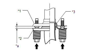
| *1 | Center Exhaust Pipe Assembly (TWC: Rear Catalyst) |
| *2 | Front No. 3 Exhaust Pipe Sub-assembly |
| *3 | Exhaust Pipe Gasket |
| *a | Space between Flanges: 8.5 mm (0.335 in.) |
(h) Connect the heated oxygen sensor (for Bank 1) connector.
(i) Engage the 4 wire harness clamps.
13. INSTALL FRONT FLOOR COVER LH
(a) Install the front floor cover LH with the 2 clips (B).
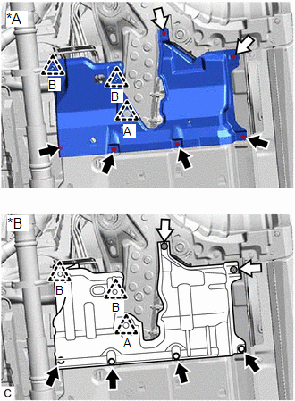
| *A | for TMC Made |
| *B | for TMMC Made |
| | Bolt |
| | Screw |
(b) Install the clip (A), 2 screws and 4 bolts to the front floor cover LH.
14. INSTALL AIR FUEL RATIO SENSOR (for Bank 1)
Click here
15. INSTALL NO. 2 ENGINE UNDER COVER
Click here
16. ADD ENGINE COOLANT
Click here
17. INSPECT FOR COOLANT LEAK
Click here
18. INSPECT FOR EXHAUST GAS LEAK
Click here
 Components
COMPONENTS ILLUSTRATION *A for TMC Made - - *1 NO. 2 ENGINE UNDER COVER *2 FRONT FLOOR COVER LH ILLUSTRATION *A for TMMC Made - - *1 NO. 2 ENGINE UNDER COVER * ...
 Removal
REMOVAL CAUTION / NOTICE / HINT The necessary procedures (adjustment, calibration, initialization or registration) that must be performed after parts are removed and installed, or replaced during exha ...
Other materials:
Lexus RX (RX 350L, RX450h) 2016-2026 Repair Manual > Dynamic Radar Cruise Control System: Brake Switch "A" Circuit Open (P057113)
DESCRIPTION When the brakes are applied by the dynamic radar cruise control system, the skid control ECU (brake actuator assembly) operates the stop light switch assembly (stop light control relay) to illuminate the stop lights. If the ECM receives a signal from the skid control ECU (brake actuator ...
Lexus RX (RX 350L, RX450h) 2016-2026 Owners Manual > Specifications: Tire information
Typical tire symbols
Full-size tire
Compact spare tire
Tire size
DOT and Tire Identification Number (TIN)
Location of treadwear indicators
Tire ply composition and materials
Plies are layers of rubber-coated parallel cords. Cords are the strands
which form the
plies in a tire. ...
Lexus RX (RX 350L, RX450h) 2016-{YEAR} Owners Manual
- For your information
- Pictorial index
- For safety and security
- Instrument cluster
- Operation of each component
- Driving
- Lexus Display Audio system
- Interior features
- Maintenance and care
- When trouble arises
- Vehicle specifications
- For owners
Lexus RX (RX 350L, RX450h) 2016-{YEAR} Repair Manual

0.1897