Lexus RX (RX 350L, RX450h) 2016-2026 Repair Manual: Terminals Of Ecu
TERMINALS OF ECU
CHECK ECM
HINT:
As a waterproof connector is used for the ECM, voltage, resistance and waveform inspections cannot be performed. The voltage, resistance and waveform values are provided for reference only.
(a) Measure the voltage and resistance according to the value(s) in the table below.
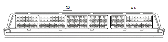
| Terminal No. (Symbol) | Wiring Color | Terminal Description | Condition | Specified Condition |
|---|---|---|---|---|
| A37-27 (STP) - D2-53 (E1) | Y - BR | Stop light switch assembly signal | Brake pedal depressed | 11 to 14 V |
| Brake pedal released | Below 1 V | |||
| A37-41 (CCS) - D2-53 (E1) | B - BR | Cruise control main switch circuit | Cruise control main switch (ON/OFF button) not pushed | 1 MΩ or higher |
| Cruise control main switch (ON/OFF button) pushed | Below 2.5 Ω | |||
| +RES switch ON | 235 to 245 Ω | |||
| -SET switch ON | 617 to 643 Ω | |||
| CANCEL switch ON | 1509 to 1571 Ω | |||
| A37-42 (ST1-) - D2-53 (E1) | BR - BR | Stop light switch assembly signal | Engine switch on (IG), brake pedal depressed | Below 1 V |
| Engine switch on (IG), brake pedal released | 11 to 14 V |
CHECK FORWARD RECOGNITION CAMERA

NOTICE:
- DTCs may be output when connectors are disconnected during inspection. Therefore, be sure to clear the DTCs using the Techstream once the inspection has been completed.
- Do not apply excessive force to the forward recognition camera connector.
(a) Measure the voltage and resistance according to the value(s) in the table below.
| Terminal No. (Symbol) | Wiring Color | Terminal Description | Condition | Specified Condition |
|---|---|---|---|---|
| U14-3 (LKSW) - U14-10 (GND) | GR - BR | Steering pad switch assembly signal (distance control signal) | Engine switch on (IG), steering pad switch assembly (vehicle-to-vehicle distance control switch) on | Below 1 V |
| Engine switch on (IG), steering pad switch assembly (vehicle-to-vehicle distance control switch) off | 4.75 to 5.25 V | |||
| U14-7 (IGB) - U14-10 (GND) | SB - BR | Power source | Engine switch on (IG) | 11 to 14 V |
| Engine switch off | Below 1 V | |||
| U14-8 (BZ) - U14-10 (GND) | W - BR | Skid control buzzer assembly output | Engine switch on (IG), buzzer not sounding | 11 to 14 V |
| Engine switch on (IG), buzzer sounding | Below 1 V | |||
| U14-10 (GND) - Body ground | BR - Body ground | Ground | Always | Below 1 Ω |
(b) Check for pulses according to the value(s) in the table below.
HINT:
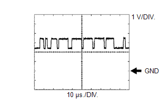
If the waveform is not similar to that shown in the illustration, a malfunction of a CAN bus line, terminating resistor, or the forward recognition camera is suspected.
| Terminal No. (Symbol) | Wiring Color | Terminal Description | Condition | Specified Condition |
|---|---|---|---|---|
| U14-5 (CA1P) - U14-10 (GND) | V - BR | CAN communication signal | Engine switch on (IG) | Pulse generation (See waveform 1) |
| U14-6 (CANH) - U14-10 (GND) | B - BR | CAN communication signal | Engine switch on (IG) | Pulse generation (See waveform 1) |
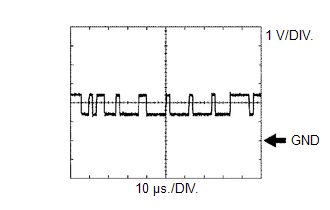
| U14-11 (CA1N) - U14-10 (GND) | P - BR | CAN communication signal | Engine switch on (IG) | Pulse generation (See waveform 2) |
| U14-12 (CANL) - U14-10 (GND) | W - BR | CAN communication signal | Engine switch on (IG) | Pulse generation (See waveform 2) |
(1) Waveform 1
| Item | Content |
|---|---|
| Tester Connection |
|
| Tool Setting | 1 V/DIV., 10 μs./DIV. |
| Condition | Engine switch on (IG) |
HINT:
The waveform varies depending on the CAN communication signal.
(2) Waveform 2
| Item | Content |
|---|---|
| Tester Connection |
|
| Tool Setting | 1 V/DIV., 10 μs./DIV. |
| Condition | Engine switch on (IG) |
HINT:
The waveform varies depending on the CAN communication signal.
 Diagnosis System
DIAGNOSIS SYSTEM DIAGNOSIS FUNCTION (a) The diagnosis function turns off the cruise control indicator, illuminates the master warning light and displays a warning message when a malfunction is detecte ...
 Dtc Check / Clear
DTC CHECK / CLEAR NOTICE: When the diagnosis system is changed from normal mode to check mode or vice versa, all DTCs and freeze frame data recorded in normal mode are cleared. Before changing modes, ...
Other materials:
Lexus RX (RX 350L, RX450h) 2016-2026 Repair Manual > Seat Belt Warning System: System Diagram
SYSTEM DIAGRAM FRONT SEAT BELT WARNING Communication Table Sender Receiver Signal Communication Method Airbag sensor assembly Combination meter assembly
Front seat inner belt assembly LH buckle switch
Front seat inner belt assembly RH buckle switch
Occupant detection signal ...
Lexus RX (RX 350L, RX450h) 2016-2026 Repair Manual > Power Steering System: Diagnostic Trouble Code Chart
DIAGNOSTIC TROUBLE CODE CHART Power Steering System DTC No. Detection Item DTC Detection Condition Warning Indicate Return-to-normal Condition Note Link C1511 Torque Sensor1 Torque sensor malfunction EPS warning light: Comes on The ECU judges the system has returned to nor ...
Lexus RX (RX 350L, RX450h) 2016-{YEAR} Owners Manual
- For your information
- Pictorial index
- For safety and security
- Instrument cluster
- Operation of each component
- Driving
- Lexus Display Audio system
- Interior features
- Maintenance and care
- When trouble arises
- Vehicle specifications
- For owners
Lexus RX (RX 350L, RX450h) 2016-{YEAR} Repair Manual

0.0113