Lexus RX (RX 350L, RX450h) 2016-2026 Repair Manual: Removal
REMOVAL
CAUTION / NOTICE / HINT
The necessary procedures (adjustment, calibration, initialization or registration) that must be performed after parts are removed and installed, or replaced during generator assembly removal/installation are shown below.
Necessary Procedures After Parts Removed/Installed/Replaced| Replaced Part or Performed Procedure | Necessary Procedure | Effect/Inoperative Function when Necessary Procedure not Performed | Link |
|---|---|---|---|
| Battery terminal is disconnected/reconnected | Memorize steering angle neutral point | Lane Control System | |
| Pre-collision system | |||
| Intelligent clearance sonar system*1 | |||
| Parking assist monitor system | | ||
| Panoramic view monitor system | | ||
| Lighting system (w/ Automatic Headlight Beam Level Control System) | | ||
| Initialize back door lock | Power door lock control system | | |
| Reset back door close position | Power back door system | |
*1: When performing learning using the Techstream.
Click here .gif)
PROCEDURE
1. PRECAUTION
NOTICE:
After turning the engine switch off, waiting time may be required before disconnecting the cable from the negative (-) battery terminal. Therefore, make sure to read the disconnecting the cable from the negative (-) battery terminal notices before proceeding with work.
Click here
2. DISCONNECT CABLE FROM NEGATIVE BATTERY TERMINAL
NOTICE:
When disconnecting the cable, some systems need to be initialized after the cable is reconnected.
Click here
3. REMOVE RADIATOR ASSEMBLY
Click here
4. REMOVE V-RIBBED BELT
Click here
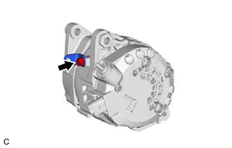
5. REMOVE GENERATOR ASSEMBLY
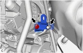
| (a) Open the terminal cap. |
|
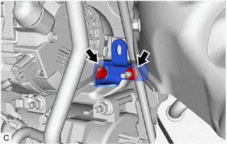
(b) Remove the nut and disconnect the wire harness from terminal B.
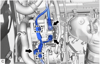
(c) Disconnect the generator assembly connector.
(d) Disconnect the compressor and magnetic clutch connector.
(e) Disengage the 2 wire harness clamps.
| (f) Type A: (1) Remove the 2 bolts and generator assembly bracket. |
|
(g) Type B:
| (1) Remove the bolt, nut and generator assembly bracket. |
|
| (h) Remove the 2 bolts and generator assembly. |
|
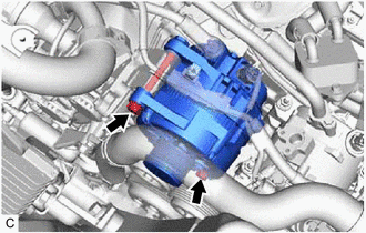
| (i) Remove the bolt and wire harness clamp bracket. |
|
 Components
COMPONENTS ILLUSTRATION *A Type A *B Type B *1 GENERATOR ASSEMBLY *2 WIRE HARNESS CLAMP BRACKET *3 TERMINAL CAP *4 GENERATOR ASSEMBLY BRACKET N*m (kgf*cm, ft.*lbf) ...
 Disassembly
DISASSEMBLY PROCEDURE 1. REMOVE GENERATOR PULLEY CAP (a) Using a screwdriver, remove the generator pulley cap from the generator pulley with clutch. NOTICE: Do not reuse the generator pulley cap. ...
Other materials:
Lexus RX (RX 350L, RX450h) 2016-2026 Repair Manual > Front Power Seat Control System (w/ Memory): Diagnosis System
DIAGNOSIS SYSTEM DESCRIPTION (a) Front power seat control system (w/ Memory) data and Diagnostic Trouble Codes (DTCs) can be read through the Data Link Connector 3 (DLC3) of the vehicle. When the system seems to be malfunctioning, use the Techstream to check for malfunctions and perform repairs. CHE ...
Lexus RX (RX 350L, RX450h) 2016-2026 Repair Manual > Navigation System: Visual Mute Signal Circuit between Radio Receiver and Multi-display
DESCRIPTION The radio receiver assembly sends a visual mute signal to the multi-display assembly. As a result, a black screen is displayed when the screen changes so that noise and distorted images are not displayed. When an open exists in the circuit, noise and distorted images will be displayed in ...
Lexus RX (RX 350L, RX450h) 2016-{YEAR} Owners Manual
- For your information
- Pictorial index
- For safety and security
- Instrument cluster
- Operation of each component
- Driving
- Lexus Display Audio system
- Interior features
- Maintenance and care
- When trouble arises
- Vehicle specifications
- For owners
Lexus RX (RX 350L, RX450h) 2016-{YEAR} Repair Manual

0.0113