Lexus RX (RX 350L, RX450h) 2016-2026 Repair Manual: Lost Communication with Gateway Module (Main Body ECU) (U1002)
DESCRIPTION
- The main body ECU (multiplex network body ECU) will store this DTC when no signals can be received from the ECUs that have been memorized as those that are connected to sub bus 1.
- When the main body ECU (multiplex network body ECU) receives a response signal from the ECUs connected to sub bus 1, the main body ECU (multiplex network body ECU) recognizes and memorizes that the ECU is connected to sub bus 1. Based on this memorized data, the main body ECU (multiplex network body ECU) monitors for malfunctions in the ECUs connected to sub bus 1 when communicating with those ECUs. If the main body ECU (multiplex network body ECU) cannot receive response signals from the ECUs that have been memorized as those connected to sub bus 1, the main body ECU (multiplex network body ECU) determines that a malfunction exists.
| DTC No. | Detection Item | DTC Detection Condition | Trouble Area | Note |
|---|---|---|---|---|
| U1002 | Lost Communication with Gateway Module (Main Body ECU) | The main body ECU (multiplex network body ECU) cannot receive signals from all ECUs that have been memorized as those connected to sub bus 1. |
| HINT: The main body ECU (multiplex network body ECU) stores DTCs when it detects a communication stop or network communication error for ECUs connected to sub bus 1. |
HINT:
This diagnostic procedure is for when DTC U1002 is output by the main body ECU (multiplex network body ECU) (Techstream display: Main Body).
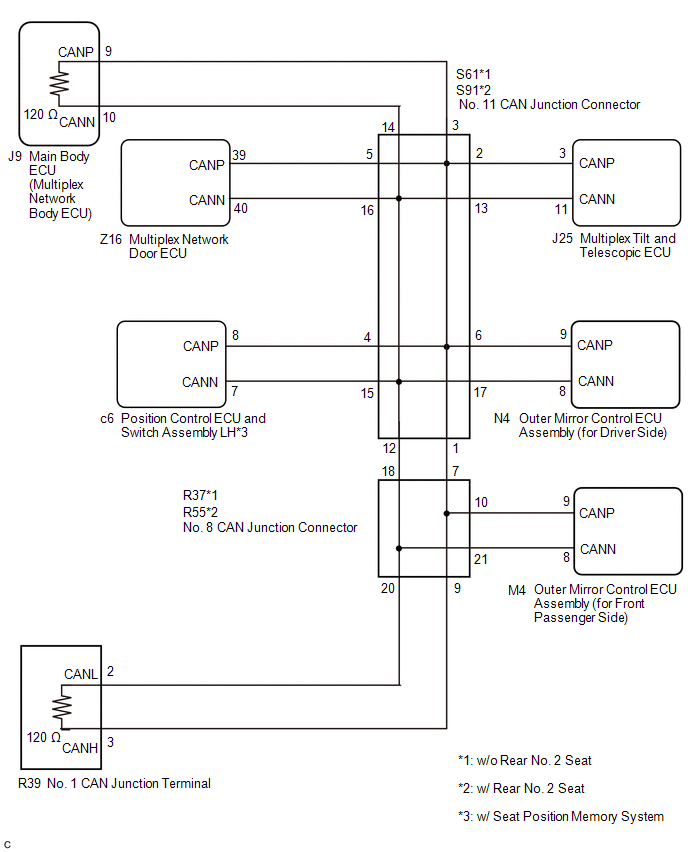
WIRING DIAGRAM
CAUTION / NOTICE / HINT
NOTICE:
- Before measuring the resistance of the CAN bus, turn the engine switch off and leave the vehicle for 1 minute or more without operating the key or any switches, or opening or closing the doors. After that, disconnect the cable from the negative (-) battery terminal and leave the vehicle for 1 minute or more before measuring the resistance.
-
After turning the engine switch off, waiting time may be required before disconnecting the cable from the negative (-) battery terminal. Therefore, make sure to read the disconnecting the cable from the negative (-) battery terminal notices before proceeding with work.
Click here
.gif)
-
Because the order of diagnosis is important to allow correct diagnosis, make sure to begin troubleshooting using How to Proceed with Troubleshooting when CAN communication system related DTCs are output.
Click here
- After performing repairs, perform the DTC check procedure and confirm that the DTCs are not output again.
- DTC check procedure: Turn the engine switch on (IG) and wait for at least 20 seconds.
-
After the repair, perform the CAN bus check and check that all the ECUs and sensors connected to the CAN communication system are displayed.
Click here
-
If the main body ECU (multiplex network body ECU) is replaced, refer to Registration.
Click here
HINT:
- Operating the engine switch, any other switches or a door triggers related ECU and sensor communication on the CAN. This communication will cause the resistance value to change.
- Even after DTCs are cleared, if a DTC is stored again after driving the vehicle for a while, the malfunction may be occurring due to vibration of the vehicle. In such a case, wiggling the ECUs or wire harness while performing the inspection below may help determine the cause of the malfunction.
PROCEDURE
| 1. | CHECK SUB BUS 1 |
(a) Disconnect the cable from the negative (-) battery terminal.
| (b) Measure the resistance according to the value(s) in the table below. Standard Resistance: for DLC3 Connector Type A
|
|

| Result | Proceed to |
|---|---|
| OK | A |
| Open circuit in CAN main bus lines | B |
| Short circuit between bus lines | C |
| D |
| B | .gif) | GO TO STEP 3 |
| C | | GO TO STEP 9 |
| D | | GO TO STEP 16 |
|
.gif)
| 2. | CHECK FOR DTC OUTPUT |
(a) Reconnect the cable to the negative (-) battery terminal.
(b) Connect the Techstream to the DLC3.
(c) Turn the engine switch on (IG).
(d) Turn the Techstream on.
(e) Clear the DTCs.
Body Electrical > Main Body > Clear DTCs(f) Turn the engine switch off.
(g) Turn the engine switch on (IG).
(h) Check for DTCs.
Body Electrical > Main Body > Trouble Codes| Result | Proceed to |
|---|---|
| DTC U1002 is not output from the main body ECU (multiplex network body ECU) (Techstream display: Main Body) | A |
| DTC U1002 is output from the main body ECU (multiplex network body ECU) (Techstream display: Main Body) | B |
| A | | SYMPTOM SIMULATION |
| B | | REPLACE MAIN BODY ECU (MULTIPLEX NETWORK BODY ECU) |
| 3. | CHECK FOR OPEN IN SUB BUS 1 LINES (MAIN BODY ECU (MULTIPLEX NETWORK BODY ECU)) |
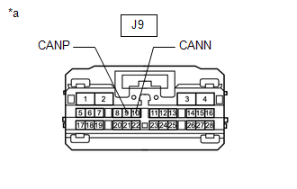
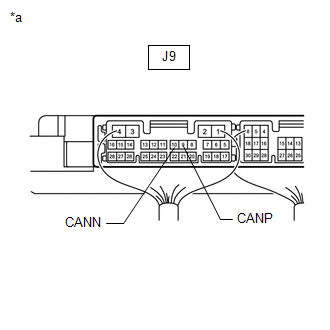
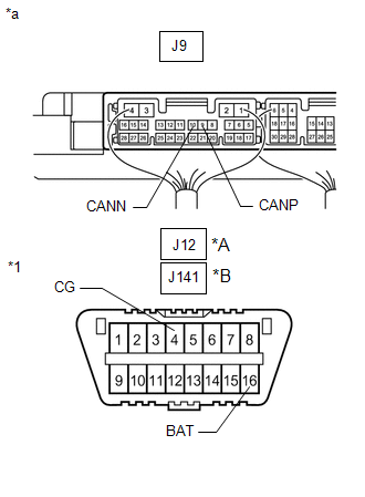
| (a) Disconnect the J9 main body ECU (multiplex network body ECU) connector. |
|
(b) Measure the resistance according to the value(s) in the table below.
Standard Resistance:
| Tester Connection | Condition | Specified Condition |
|---|---|---|
| J9-9 (CANP) - J9-10 (CANN) | Cable disconnected from negative (-) battery terminal | 108 to 132 Ω |
| OK | | REPLACE MAIN BODY ECU (MULTIPLEX NETWORK BODY ECU) |
|
| 4. | CHECK FOR OPEN IN SUB BUS 1 LINES (NO. 1 CAN JUNCTION TERMINAL) |
(a) Reconnect the J9 main body ECU (multiplex network body ECU) connector.
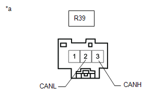
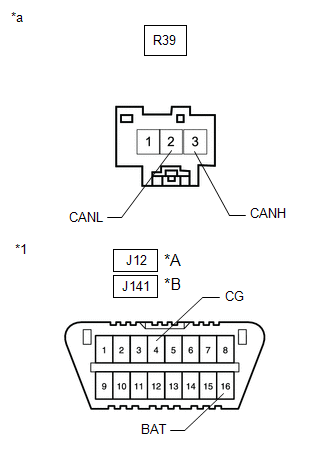
| (b) Disconnect the R39 No. 1 CAN junction terminal connector. |
|

(c) Measure the resistance according to the value(s) in the table below.
Standard Resistance:
| Tester Connection | Condition | Specified Condition |
|---|---|---|
| R39-3 (CANH) - R39-2 (CANL) | Cable disconnected from negative (-) battery terminal | 108 to 132 Ω |
| Result | Proceed to |
|---|---|
| OK | A |
| NG (w/o Rear No. 2 Seat) | B |
| NG (w/ Rear No. 2 Seat) | C |
| A | | REPLACE NO. 1 CAN JUNCTION TERMINAL |
| C | | GO TO STEP 7 |
|
| 5. | CHECK FOR OPEN IN SUB BUS 1 LINES (NO. 11 CAN JUNCTION CONNECTOR) |
(a) Reconnect the R39 No. 1 CAN junction terminal connector.
| (b) Disconnect the S61 No. 11 CAN junction connector. |
|

(c) Measure the resistance according to the value(s) in the table below.
Standard Resistance:
| Tester Connection | Condition | Specified Condition | Connected to |
|---|---|---|---|
| S61-1 (CANH) - S61-12 (CANL) | Cable disconnected from negative (-) battery terminal | 108 to 132 Ω | No. 8 CAN junction connector |
| S61-3 (CANH) - S61-14 (CANL) | Cable disconnected from negative (-) battery terminal | 108 to 132 Ω | Main body ECU (multiplex network body ECU) |
| Result | Proceed to |
|---|---|
| OK | A |
| NG (Main body ECU (multiplex network body ECU) main lines) | B |
| NG (No. 8 CAN junction connector main lines) | C |
| A | | REPLACE NO. 11 CAN JUNCTION CONNECTOR |
| B | | REPAIR OR REPLACE CAN MAIN BUS LINES OR CONNECTOR (NO. 11 CAN JUNCTION CONNECTOR - MAIN BODY ECU (MULTIPLEX NETWORK BODY ECU)) |
|
| 6. | CHECK FOR OPEN IN SUB BUS 1 LINES (NO. 8 CAN JUNCTION CONNECTOR) |
(a) Reconnect the S61 No. 11 CAN junction connector.
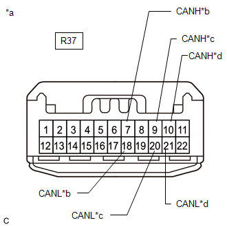
| (b) Disconnect the R37 No. 8 CAN junction connector. |
|

(c) Measure the resistance according to the value(s) in the table below.
Standard Resistance:
| Tester Connection | Condition | Specified Condition | Connected to |
|---|---|---|---|
| R37-7 (CANH) - R37-18 (CANL) | Cable disconnected from negative (-) battery terminal | 108 to 132 Ω | No. 11 CAN junction connector |
| R37-9 (CANH) - R37-20 (CANL) | Cable disconnected from negative (-) battery terminal | 108 to 132 Ω | No. 1 CAN junction terminal |
| Result | Proceed to |
|---|---|
| OK | A |
| NG (No. 1 CAN junction terminal main lines) | B |
| NG (No. 11 CAN junction connector main lines) | C |
| A | | REPLACE NO. 8 CAN JUNCTION CONNECTOR |
| B | | REPAIR OR REPLACE CAN MAIN BUS LINES OR CONNECTOR (NO. 8 CAN JUNCTION CONNECTOR - NO. 1 CAN JUNCTION TERMINAL) |
| C | | REPAIR OR REPLACE CAN MAIN BUS LINES OR CONNECTOR (NO. 8 CAN JUNCTION CONNECTOR - NO. 11 CAN JUNCTION CONNECTOR) |
| 7. | CHECK FOR OPEN IN SUB BUS 1 LINES (NO. 11 CAN JUNCTION CONNECTOR) |
(a) Reconnect the R39 No. 1 CAN junction terminal connector.
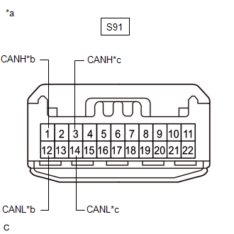
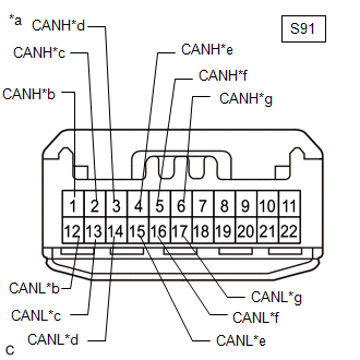
| (b) Disconnect the S91 No. 11 CAN junction connector. |
|
(c) Measure the resistance according to the value(s) in the table below.
Standard Resistance:
| Tester Connection | Condition | Specified Condition | Connected to |
|---|---|---|---|
| S91-1 (CANH) - S91-12 (CANL) | Cable disconnected from negative (-) battery terminal | 108 to 132 Ω | No. 8 CAN junction connector |
| S91-3 (CANH) - S91-14 (CANL) | Cable disconnected from negative (-) battery terminal | 108 to 132 Ω | Main body ECU (multiplex network body ECU) |
| Result | Proceed to |
|---|---|
| OK | A |
| NG (Main body ECU (multiplex network body ECU) main lines) | B |
| NG (No. 8 CAN junction connector main lines) | C |
| A | | REPLACE NO. 11 CAN JUNCTION CONNECTOR |
| B | | REPAIR OR REPLACE CAN MAIN BUS LINES OR CONNECTOR (NO. 11 CAN JUNCTION CONNECTOR - MAIN BODY ECU (MULTIPLEX NETWORK BODY ECU)) |
|
| 8. | CHECK FOR OPEN IN SUB BUS 1 LINES (NO. 8 CAN JUNCTION CONNECTOR) |
(a) Reconnect the S91 No. 11 CAN junction connector.
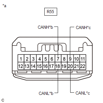
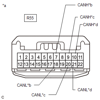
| (b) Disconnect the R55 No. 8 CAN junction connector. |
|
(c) Measure the resistance according to the value(s) in the table below.
Standard Resistance:
| Tester Connection | Condition | Specified Condition | Connected to |
|---|---|---|---|
| R55-7 (CANH) - R55-18 (CANL) | Cable disconnected from negative (-) battery terminal | 108 to 132 Ω | No. 11 CAN junction connector |
| R55-9 (CANH) - R55-20 (CANL) | Cable disconnected from negative (-) battery terminal | 108 to 132 Ω | No. 1 CAN junction terminal |
| Result | Proceed to |
|---|---|
| OK | A |
| NG (No. 1 CAN junction terminal main lines) | B |
| NG (No. 11 CAN junction connector main lines) | C |
| A | | REPLACE NO. 8 CAN JUNCTION CONNECTOR |
| B | | REPAIR OR REPLACE CAN MAIN BUS LINES OR CONNECTOR (NO. 8 CAN JUNCTION CONNECTOR - NO. 1 CAN JUNCTION TERMINAL) |
| C | | REPAIR OR REPLACE CAN MAIN BUS LINES OR CONNECTOR (NO. 8 CAN JUNCTION CONNECTOR - NO. 11 CAN JUNCTION CONNECTOR) |
| 9. | CHECK FOR SHORT IN SUB BUS 1 LINES (MAIN BODY ECU (MULTIPLEX NETWORK BODY ECU)) |
| (a) Disconnect the J9 main body ECU (multiplex network body ECU) connector. |
|

(b) Measure the resistance according to the value(s) in the table below.
Standard Resistance:
| Tester Connection | Condition | Specified Condition |
|---|---|---|
| J9-9 (CANP) - J9-10 (CANN) | Cable disconnected from negative (-) battery terminal | 108 to 132 Ω |
| OK | | REPLACE MAIN BODY ECU (MULTIPLEX NETWORK BODY ECU) |
|
| 10. | CHECK FOR SHORT IN SUB BUS 1 LINES (NO. 1 CAN JUNCTION TERMINAL) |
(a) Reconnect the J9 main body ECU (multiplex network body ECU) connector.
| (b) Disconnect the R39 No. 1 CAN junction terminal connector. |
|
(c) Measure the resistance according to the value(s) in the table below.
Standard Resistance:
| Tester Connection | Condition | Specified Condition |
|---|---|---|
| R39-3 (CANH) - R39-2 (CANL) | Cable disconnected from negative (-) battery terminal | 108 to 132 Ω |
| Result | Proceed to |
|---|---|
| OK | A |
| NG (w/o Rear No. 2 Seat) | B |
| NG (w/ Rear No. 2 Seat) | C |
| A | | REPLACE NO. 1 CAN JUNCTION TERMINAL |
| C | | GO TO STEP 13 |
|
| 11. | CHECK FOR SHORT IN SUB BUS 1 LINES (NO. 11 CAN JUNCTION CONNECTOR) |
(a) Reconnect the R39 No. 1 CAN junction terminal connector.
| (b) Disconnect the S61 No. 11 CAN junction connector. |
|

(c) Measure the resistance according to the value(s) in the table below.
Standard Resistance:
| Tester Connection | Condition | Specified Condition | Connected to |
|---|---|---|---|
| *: w/ Seat Position Memory System | |||
| S61-1 (CANH) - S61-12 (CANL) | Cable disconnected from negative (-) battery terminal | 108 to 132 Ω | No. 8 CAN junction connector |
| S61-2 (CANH) - S61-13 (CANL) | Cable disconnected from negative (-) battery terminal | 200 Ω or higher | Multiplex tilt and telescopic ECU |
| S61-3 (CANH) - S61-14 (CANL) | Cable disconnected from negative (-) battery terminal | 108 to 132 Ω | Main body ECU (multiplex network body ECU) |
| S61-4 (CANH) - S61-15 (CANL) | Cable disconnected from negative (-) battery terminal | 200 Ω or higher | Position control ECU and switch assembly LH* |
| S61-5 (CANH) - S61-16 (CANL) | Cable disconnected from negative (-) battery terminal | 200 Ω or higher | Multiplex network door ECU |
| S61-6 (CANH) - S61-17 (CANL) | Cable disconnected from negative (-) battery terminal | 200 Ω or higher | Outer mirror control ECU assembly (for driver side) |
| Result | Proceed to |
|---|---|
| OK | A |
| NG (Main body ECU (multiplex network body ECU) main lines) | B |
| NG (ECU or sensor branch lines) | C |
| NG (No. 8 CAN junction connector main lines) | D |
| A | | REPLACE NO. 11 CAN JUNCTION CONNECTOR |
| B | | REPAIR OR REPLACE CAN MAIN BUS LINES OR CONNECTOR (NO. 11 CAN JUNCTION CONNECTOR - MAIN BODY ECU (MULTIPLEX NETWORK BODY ECU)) |
| C | | GO TO STEP 15 |
|
| 12. | CHECK FOR SHORT IN SUB BUS 1 LINES (NO. 8 CAN JUNCTION CONNECTOR) |
(a) Reconnect the S61 No. 11 CAN junction connector.
| (b) Disconnect the R37 No. 8 CAN junction connector. |
|
(c) Measure the resistance according to the value(s) in the table below.
Standard Resistance:
| Tester Connection | Condition | Specified Condition | Connected to |
|---|---|---|---|
| R37-7 (CANH) - R37-18 (CANL) | Cable disconnected from negative (-) battery terminal | 108 to 132 Ω | No. 11 CAN junction connector |
| R37-9 (CANH) - R37-20 (CANL) | Cable disconnected from negative (-) battery terminal | 108 to 132 Ω | No. 1 CAN junction terminal |
| R37-10 (CANH) - R37-21 (CANL) | Cable disconnected from negative (-) battery terminal | 200 Ω or higher | Outer mirror control ECU assembly (for front passenger side) |
| Result | Proceed to |
|---|---|
| OK | A |
| NG (No. 1 CAN junction terminal main lines) | B |
| NG (ECU or sensor branch lines) | C |
| NG (No. 11 CAN junction connector main lines) | D |
| A | | REPLACE NO. 8 CAN JUNCTION CONNECTOR |
| B | | REPAIR OR REPLACE CAN MAIN BUS LINES OR CONNECTOR (NO. 8 CAN JUNCTION CONNECTOR - NO. 1 CAN JUNCTION TERMINAL) |
| C | | GO TO STEP 15 |
| D | | REPAIR OR REPLACE CAN MAIN BUS LINES OR CONNECTOR (NO. 8 CAN JUNCTION CONNECTOR - NO. 11 CAN JUNCTION CONNECTOR) |
| 13. | CHECK FOR SHORT IN SUB BUS 1 LINES (NO. 11 CAN JUNCTION CONNECTOR) |
(a) Reconnect the R39 No. 1 CAN junction terminal connector.
| (b) Disconnect the S91 No. 11 CAN junction connector. |
|
(c) Measure the resistance according to the value(s) in the table below.
Standard Resistance:
| Tester Connection | Condition | Specified Condition | Connected to |
|---|---|---|---|
| *: w/ Seat Position Memory System | |||
| S91-1 (CANH) - S91-12 (CANL) | Cable disconnected from negative (-) battery terminal | 108 to 132 Ω | No. 8 CAN junction connector |
| S91-2 (CANH) - S91-13 (CANL) | Cable disconnected from negative (-) battery terminal | 200 Ω or higher | Multiplex tilt and telescopic ECU |
| S91-3 (CANH) - S91-14 (CANL) | Cable disconnected from negative (-) battery terminal | 108 to 132 Ω | Main body ECU (multiplex network body ECU) |
| S91-4 (CANH) - S91-15 (CANL) | Cable disconnected from negative (-) battery terminal | 200 Ω or higher | Position control ECU and switch assembly LH* |
| S91-5 (CANH) - S91-16 (CANL) | Cable disconnected from negative (-) battery terminal | 200 Ω or higher | Multiplex network door ECU |
| S91-6 (CANH) - S91-17 (CANL) | Cable disconnected from negative (-) battery terminal | 200 Ω or higher | Outer mirror control ECU assembly (for driver side) |
| Result | Proceed to |
|---|---|
| OK | A |
| NG (Main body ECU (multiplex network body ECU) main lines) | B |
| NG (ECU or sensor branch lines) | C |
| NG (No. 8 CAN junction connector main lines) | D |
| A | | REPLACE NO. 11 CAN JUNCTION CONNECTOR |
| B | | REPAIR OR REPLACE CAN MAIN BUS LINES OR CONNECTOR (NO. 11 CAN JUNCTION CONNECTOR - MAIN BODY ECU (MULTIPLEX NETWORK BODY ECU)) |
| C | | GO TO STEP 15 |
|
| 14. | CHECK FOR SHORT IN SUB BUS 1 LINES (NO. 8 CAN JUNCTION CONNECTOR) |
(a) Reconnect the S91 No. 11 CAN junction connector.
| (b) Disconnect the R55 No. 8 CAN junction connector. |
|
(c) Measure the resistance according to the value(s) in the table below.
Standard Resistance:
| Tester Connection | Condition | Specified Condition | Connected to |
|---|---|---|---|
| R55-7 (CANH) - R55-18 (CANL) | Cable disconnected from negative (-) battery terminal | 108 to 132 Ω | No. 11 CAN junction connector |
| R55-9 (CANH) - R55-20 (CANL) | Cable disconnected from negative (-) battery terminal | 108 to 132 Ω | No. 1 CAN junction terminal |
| R55-10 (CANH) - R55-21 (CANL) | Cable disconnected from negative (-) battery terminal | 200 Ω or higher | Outer mirror control ECU assembly (for front passenger side) |
| Result | Proceed to |
|---|---|
| OK | A |
| NG (No. 1 CAN junction terminal main lines) | B |
| NG (ECU or sensor branch lines) | C |
| NG (No. 11 CAN junction connector main lines) | D |
| A | | REPLACE NO. 8 CAN JUNCTION CONNECTOR |
| B | | REPAIR OR REPLACE CAN MAIN BUS LINES OR CONNECTOR (NO. 8 CAN JUNCTION CONNECTOR - NO. 1 CAN JUNCTION TERMINAL) |
| D | | REPAIR OR REPLACE CAN MAIN BUS LINES OR CONNECTOR (NO. 8 CAN JUNCTION CONNECTOR - NO. 11 CAN JUNCTION CONNECTOR) |
|
| 15. | CHECK FOR SHORT IN SUB BUS 1 LINES (ECU, SENSOR) |
(a) Reconnect all wire harness connectors.
(b) Disconnect the connector that includes terminals CANH and CANL from the ECU or sensor to which the short circuited branch line is connected.
Click here
| (c) Measure the resistance according to the value(s) in the table below. Standard Resistance:
HINT: If the resistance becomes normal (between 54 and 69 Ω) when the connector is disconnected from the ECU or sensor, there may be a short in the ECU or sensor. |
|
| OK | | REPLACE CORRESPONDING ECU OR SENSOR |
| NG | | REPAIR OR REPLACE CORRESPONDING ECU OR SENSOR BRANCH LINES OR CONNECTOR |
| 16. | CHECK FOR SHORT IN SUB BUS 1 LINE (MAIN BODY ECU (MULTIPLEX NETWORK BODY ECU)) |
| (a) Disconnect the J9 main body ECU (multiplex network body ECU) connector. |
|
(b) Measure the resistance according to the value(s) in the table below.
Standard Resistance:
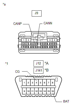
for DLC3 Connector Type A| Tester Connection | Condition | Specified Condition | Result |
|---|---|---|---|
| J9-9 (CANP) - J12-4 (CG) | Cable disconnected from negative (-) battery terminal | 200 Ω or higher | Below 200 Ω: CANH short to ground |
| J9-10 (CANN) - J12-4 (CG) | Cable disconnected from negative (-) battery terminal | 200 Ω or higher | Below 200 Ω: CANL short to ground |
| J9-9 (CANP) - J12-16 (BAT) | Cable disconnected from negative (-) battery terminal | 6 kΩ or higher | Below 6 kΩ: CANH +B short |
| J9-10 (CANN) - J12-16 (BAT) | Cable disconnected from negative (-) battery terminal | 6 kΩ or higher | Below 6 kΩ: CANL +B short |
| Tester Connection | Condition | Specified Condition | Result |
|---|---|---|---|
| J9-9 (CANP) - J141-4 (CG) | Cable disconnected from negative (-) battery terminal | 200 Ω or higher | Below 200 Ω: CANH short to ground |
| J9-10 (CANN) - J141-4 (CG) | Cable disconnected from negative (-) battery terminal | 200 Ω or higher | Below 200 Ω: CANL short to ground |
| J9-9 (CANP) - J141-16 (BAT) | Cable disconnected from negative (-) battery terminal | 6 kΩ or higher | Below 6 kΩ: CANH +B short |
| J9-10 (CANN) - J141-16 (BAT) | Cable disconnected from negative (-) battery terminal | 6 kΩ or higher | Below 6 kΩ: CANL +B short |
HINT:
- It is only necessary to perform the inspection in the above table for the result (short circuit) that was obtained in the Check Sub Bus 1 inspection.
- Find the necessary inspection from the Result column that matches the result in the Result column from the Check Sub Bus 1 inspection.
| OK | | REPLACE MAIN BODY ECU (MULTIPLEX NETWORK BODY ECU) |
|
| 17. | CHECK FOR SHORT IN SUB BUS 1 LINE (NO. 1 CAN JUNCTION TERMINAL) |
(a) Reconnect the J9 main body ECU (multiplex network body ECU) connector.
| (b) Disconnect the R39 No. 1 CAN junction terminal connector. |
|
(c) Measure the resistance according to the value(s) in the table below.
Standard Resistance:
for DLC3 Connector Type A| Tester Connection | Condition | Specified Condition | Result |
|---|---|---|---|
| R39-3 (CANH) - J12-4 (CG) | Cable disconnected from negative (-) battery terminal | 200 Ω or higher | Below 200 Ω: CANH short to ground |
| R39-2 (CANL) - J12-4 (CG) | Cable disconnected from negative (-) battery terminal | 200 Ω or higher | Below 200 Ω: CANL short to ground |
| R39-3 (CANH) - J12-16 (BAT) | Cable disconnected from negative (-) battery terminal | 6 kΩ or higher | Below 6 kΩ: CANH +B short |
| R39-2 (CANL) - J12-16 (BAT) | Cable disconnected from negative (-) battery terminal | 6 kΩ or higher | Below 6 kΩ: CANL +B short |
| Tester Connection | Condition | Specified Condition | Result |
|---|---|---|---|
| R39-3 (CANH) - J141-4 (CG) | Cable disconnected from negative (-) battery terminal | 200 Ω or higher | Below 200 Ω: CANH short to ground |
| R39-2 (CANL) - J141-4 (CG) | Cable disconnected from negative (-) battery terminal | 200 Ω or higher | Below 200 Ω: CANL short to ground |
| R39-3 (CANH) - J141-16 (BAT) | Cable disconnected from negative (-) battery terminal | 6 kΩ or higher | Below 6 kΩ: CANH +B short |
| R39-2 (CANL) - J141-16 (BAT) | Cable disconnected from negative (-) battery terminal | 6 kΩ or higher | Below 6 kΩ: CANL +B short |
HINT:
- It is only necessary to perform the inspection in the above table for the result (short circuit) that was obtained in the Check Sub Bus 1 inspection.
- Find the necessary inspection from the Result column that matches the result in the Result column from the Check Sub Bus 1 inspection.
| Result | Proceed to |
|---|---|
| OK | A |
| NG (w/o Rear No. 2 Seat) | B |
| NG (w/ Rear No. 2 Seat) | C |
| A | | REPLACE NO. 1 CAN JUNCTION TERMINAL |
| C | | GO TO STEP 20 |
|
| 18. | CHECK FOR SHORT IN SUB BUS 1 LINE (NO. 11 CAN JUNCTION CONNECTOR) |
(a) Reconnect the R39 No. 1 CAN junction terminal connector.
(b) Disconnect the S61 No. 11 CAN junction connector.
(c) Measure the resistance according to the value(s) in the table below.
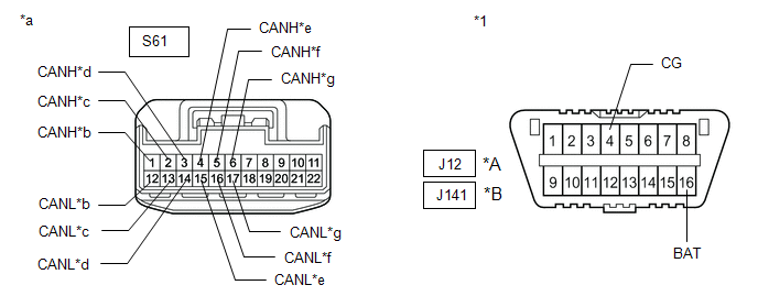
| *A | for DLC3 Connector Type A | *B | for DLC3 Connector Type B |
| *1 | DLC3 | - | - |
| *a | Front view of wire harness connector (to No. 11 CAN Junction Connector) | *b | to No. 8 CAN Junction Connector |
| *c | to Multiplex Tilt and Telescopic ECU | *d | to Main Body ECU (Multiplex Network Body ECU) |
| *e | to Position Control ECU and Switch Assembly LH (w/ Seat Position Memory System) | *f | to Multiplex Network Door ECU |
| *g | to Outer Mirror Control ECU Assembly (for Driver Side) | - | - |
Standard Resistance:
for DLC3 Connector Type A| Tester Connection | Condition | Specified Condition | Result | Connected to |
|---|---|---|---|---|
| *: w/ Seat Position Memory System | ||||
| S61-1 (CANH) - J12-4 (CG) | Cable disconnected from negative (-) battery terminal | 200 Ω or higher | Below 200 Ω: CANH short to ground | No. 8 CAN junction connector |
| S61-12 (CANL) - J12-4 (CG) | Cable disconnected from negative (-) battery terminal | 200 Ω or higher | Below 200 Ω: CANL short to ground | |
| S61-2 (CANH) - J12-4 (CG) | Cable disconnected from negative (-) battery terminal | 200 Ω or higher | Below 200 Ω: CANH short to ground | Multiplex tilt and telescopic ECU |
| S61-13 (CANL) - J12-4 (CG) | Cable disconnected from negative (-) battery terminal | 200 Ω or higher | Below 200 Ω: CANL short to ground | |
| S61-3 (CANH) - J12-4 (CG) | Cable disconnected from negative (-) battery terminal | 200 Ω or higher | Below 200 Ω: CANH short to ground | Main body ECU (Multiplex network body ECU) |
| S61-14 (CANL) - J12-4 (CG) | Cable disconnected from negative (-) battery terminal | 200 Ω or higher | Below 200 Ω: CANL short to ground | |
| S61-4 (CANH) - J12-4 (CG) | Cable disconnected from negative (-) battery terminal | 200 Ω or higher | Below 200 Ω: CANH short to ground | Position control ECU and switch assembly LH* |
| S61-15 (CANL) - J12-4 (CG) | Cable disconnected from negative (-) battery terminal | 200 Ω or higher | Below 200 Ω: CANL short to ground | |
| S61-5 (CANH) - J12-4 (CG) | Cable disconnected from negative (-) battery terminal | 200 Ω or higher | Below 200 Ω: CANH short to ground | Multiplex network door ECU |
| S61-16 (CANL) - J12-4 (CG) | Cable disconnected from negative (-) battery terminal | 200 Ω or higher | Below 200 Ω: CANL short to ground | |
| S61-6 (CANH) - J12-4 (CG) | Cable disconnected from negative (-) battery terminal | 200 Ω or higher | Below 200 Ω: CANH short to ground | Outer mirror control ECU assembly (for driver side) |
| S61-17 (CANL) - J12-4 (CG) | Cable disconnected from negative (-) battery terminal | 200 Ω or higher | Below 200 Ω: CANL short to ground | |
| S61-1 (CANH) - J12-16 (BAT) | Cable disconnected from negative (-) battery terminal | 6 kΩ or higher | Below 6 kΩ: CANH +B short | No. 8 CAN junction connector |
| S61-12 (CANL) - J12-16 (BAT) | Cable disconnected from negative (-) battery terminal | 6 kΩ or higher | Below 6 kΩ: CANL +B short | |
| S61-2 (CANH) - J12-16 (BAT) | Cable disconnected from negative (-) battery terminal | 6 kΩ or higher | Below 6 kΩ: CANH +B short | Multiplex tilt and telescopic ECU |
| S61-13 (CANL) - J12-16 (BAT) | Cable disconnected from negative (-) battery terminal | 6 kΩ or higher | Below 6 kΩ: CANL +B short | |
| S61-3 (CANH) - J12-16 (BAT) | Cable disconnected from negative (-) battery terminal | 6 kΩ or higher | Below 6 kΩ: CANH +B short | Main body ECU (Multiplex network body ECU) |
| S61-14 (CANL) - J12-16 (BAT) | Cable disconnected from negative (-) battery terminal | 6 kΩ or higher | Below 6 kΩ: CANL +B short | |
| S61-4 (CANH) - J12-16 (BAT) | Cable disconnected from negative (-) battery terminal | 6 kΩ or higher | Below 6 kΩ: CANH +B short | Position control ECU and switch assembly LH* |
| S61-15 (CANL) - J12-16 (BAT) | Cable disconnected from negative (-) battery terminal | 6 kΩ or higher | Below 6 kΩ: CANL +B short | |
| S61-5 (CANH) - J12-16 (BAT) | Cable disconnected from negative (-) battery terminal | 6 kΩ or higher | Below 6 kΩ: CANH +B short | Multiplex network door ECU |
| S61-16 (CANL) - J12-16 (BAT) | Cable disconnected from negative (-) battery terminal | 6 kΩ or higher | Below 6 kΩ: CANL +B short | |
| S61-6 (CANH) - J12-16 (BAT) | Cable disconnected from negative (-) battery terminal | 6 kΩ or higher | Below 6 kΩ: CANH +B short | Outer mirror control ECU assembly (for driver side) |
| S61-17 (CANL) - J12-16 (BAT) | Cable disconnected from negative (-) battery terminal | 6 kΩ or higher | Below 6 kΩ: CANL +B short | |
| Tester Connection | Condition | Specified Condition | Result | Connected to |
|---|---|---|---|---|
| *: w/ Seat Position Memory System | ||||
| S61-1 (CANH) - J141-4 (CG) | Cable disconnected from negative (-) battery terminal | 200 Ω or higher | Below 200 Ω: CANH short to ground | No. 8 CAN junction connector |
| S61-12 (CANL) - J141-4 (CG) | Cable disconnected from negative (-) battery terminal | 200 Ω or higher | Below 200 Ω: CANL short to ground | |
| S61-2 (CANH) - J141-4 (CG) | Cable disconnected from negative (-) battery terminal | 200 Ω or higher | Below 200 Ω: CANH short to ground | Multiplex tilt and telescopic ECU |
| S61-13 (CANL) - J141-4 (CG) | Cable disconnected from negative (-) battery terminal | 200 Ω or higher | Below 200 Ω: CANL short to ground | |
| S61-3 (CANH) - J141-4 (CG) | Cable disconnected from negative (-) battery terminal | 200 Ω or higher | Below 200 Ω: CANH short to ground | Main body ECU (Multiplex network body ECU) |
| S61-14 (CANL) - J141-4 (CG) | Cable disconnected from negative (-) battery terminal | 200 Ω or higher | Below 200 Ω: CANL short to ground | |
| S61-4 (CANH) - J141-4 (CG) | Cable disconnected from negative (-) battery terminal | 200 Ω or higher | Below 200 Ω: CANH short to ground | Position control ECU and switch assembly LH* |
| S61-15 (CANL) - J141-4 (CG) | Cable disconnected from negative (-) battery terminal | 200 Ω or higher | Below 200 Ω: CANL short to ground | |
| S61-5 (CANH) - J141-4 (CG) | Cable disconnected from negative (-) battery terminal | 200 Ω or higher | Below 200 Ω: CANH short to ground | Multiplex network door ECU |
| S61-16 (CANL) - J141-4 (CG) | Cable disconnected from negative (-) battery terminal | 200 Ω or higher | Below 200 Ω: CANL short to ground | |
| S61-6 (CANH) - J141-4 (CG) | Cable disconnected from negative (-) battery terminal | 200 Ω or higher | Below 200 Ω: CANH short to ground | Outer mirror control ECU assembly (for driver side) |
| S61-17 (CANL) - J141-4 (CG) | Cable disconnected from negative (-) battery terminal | 200 Ω or higher | Below 200 Ω: CANL short to ground | |
| S61-1 (CANH) - J141-16 (BAT) | Cable disconnected from negative (-) battery terminal | 6 kΩ or higher | Below 6 kΩ: CANH +B short | No. 8 CAN junction connector |
| S61-12 (CANL) - J141-16 (BAT) | Cable disconnected from negative (-) battery terminal | 6 kΩ or higher | Below 6 kΩ: CANL +B short | |
| S61-2 (CANH) - J141-16 (BAT) | Cable disconnected from negative (-) battery terminal | 6 kΩ or higher | Below 6 kΩ: CANH +B short | Multiplex tilt and telescopic ECU |
| S61-13 (CANL) - J141-16 (BAT) | Cable disconnected from negative (-) battery terminal | 6 kΩ or higher | Below 6 kΩ: CANL +B short | |
| S61-3 (CANH) - J141-16 (BAT) | Cable disconnected from negative (-) battery terminal | 6 kΩ or higher | Below 6 kΩ: CANH +B short | Main body ECU (Multiplex network body ECU) |
| S61-14 (CANL) - J141-16 (BAT) | Cable disconnected from negative (-) battery terminal | 6 kΩ or higher | Below 6 kΩ: CANL +B short | |
| S61-4 (CANH) - J141-16 (BAT) | Cable disconnected from negative (-) battery terminal | 6 kΩ or higher | Below 6 kΩ: CANH +B short | Position control ECU and switch assembly LH* |
| S61-15 (CANL) - J141-16 (BAT) | Cable disconnected from negative (-) battery terminal | 6 kΩ or higher | Below 6 kΩ: CANL +B short | |
| S61-5 (CANH) - J141-16 (BAT) | Cable disconnected from negative (-) battery terminal | 6 kΩ or higher | Below 6 kΩ: CANH +B short | Multiplex network door ECU |
| S61-16 (CANL) - J141-16 (BAT) | Cable disconnected from negative (-) battery terminal | 6 kΩ or higher | Below 6 kΩ: CANL +B short | |
| S61-6 (CANH) - J141-16 (BAT) | Cable disconnected from negative (-) battery terminal | 6 kΩ or higher | Below 6 kΩ: CANH +B short | Outer mirror control ECU assembly (for driver side) |
| S61-17 (CANL) - J141-16 (BAT) | Cable disconnected from negative (-) battery terminal | 6 kΩ or higher | Below 6 kΩ: CANL +B short | |
HINT:
- It is only necessary to perform the inspection in the above table for the result (short circuit) that was obtained in the Check Sub Bus 1 inspection.
- Find the necessary inspection from the Result column that matches the result in the Result column from the Check Sub Bus 1 inspection.
| Result | Proceed to |
|---|---|
| OK | A |
| NG (Main body ECU (multiplex network body ECU) main line) | B |
| NG (ECU or sensor branch line) | C |
| NG (No. 8 CAN junction connector main line) | D |
| A | | REPLACE NO. 11 CAN JUNCTION CONNECTOR |
| B | | REPAIR OR REPLACE CAN MAIN BUS LINE OR CONNECTOR (NO. 11 CAN JUNCTION CONNECTOR - MAIN BODY ECU (MULTIPLEX NETWORK BODY ECU)) |
| C | | GO TO STEP 22 |
|
| 19. | CHECK FOR SHORT IN SUB BUS 1 LINE (NO. 8 CAN JUNCTION CONNECTOR) |
(a) Reconnect the S61 No. 11 CAN junction connector.
(b) Disconnect the R37 No. 8 CAN junction connector.
(c) Measure the resistance according to the value(s) in the table below.
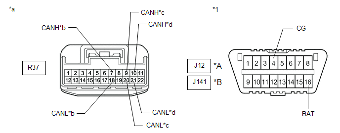
| *A | for DLC3 Connector Type A | *B | for DLC3 Connector Type B |
| *1 | DLC3 | - | - |
| *a | Front view of wire harness connector (to No. 8 CAN Junction Connector) | *b | to No. 11 CAN Junction Connector |
| *c | to No. 1 CAN Junction Terminal | *d | to Outer Mirror Control ECU Assembly (for Front Passenger Side) |
Standard Resistance:
for DLC3 Connector Type A| Tester Connection | Condition | Specified Condition | Result | Connected to |
|---|---|---|---|---|
| R37-7 (CANH) - J12-4 (CG) | Cable disconnected from negative (-) battery terminal | 200 Ω or higher | Below 200 Ω: CANH short to ground | No. 11 CAN junction connector |
| R37-18 (CANL) - J12-4 (CG) | Cable disconnected from negative (-) battery terminal | 200 Ω or higher | Below 200 Ω: CANL short to ground | |
| R37-9 (CANH) - J12-4 (CG) | Cable disconnected from negative (-) battery terminal | 200 Ω or higher | Below 200 Ω: CANH short to ground | No. 1 CAN junction terminal |
| R37-20 (CANL) - J12-4 (CG) | Cable disconnected from negative (-) battery terminal | 200 Ω or higher | Below 200 Ω: CANL short to ground | |
| R37-10 (CANH) - J12-4 (CG) | Cable disconnected from negative (-) battery terminal | 200 Ω or higher | Below 200 Ω: CANH short to ground | Outer mirror control ECU assembly (for front passenger side) |
| R37-21 (CANL) - J12-4 (CG) | Cable disconnected from negative (-) battery terminal | 200 Ω or higher | Below 200 Ω: CANL short to ground | |
| R37-7 (CANH) - J12-16 (BAT) | Cable disconnected from negative (-) battery terminal | 6 kΩ or higher | Below 6 kΩ: CANH +B short | No. 11 CAN junction connector |
| R37-18 (CANL) - J12-16 (BAT) | Cable disconnected from negative (-) battery terminal | 6 kΩ or higher | Below 6 kΩ: CANL +B short | |
| R37-9 (CANH) - J12-16 (BAT) | Cable disconnected from negative (-) battery terminal | 6 kΩ or higher | Below 6 kΩ: CANH +B short | No. 1 CAN junction terminal |
| R37-20 (CANL) - J12-16 (BAT) | Cable disconnected from negative (-) battery terminal | 6 kΩ or higher | Below 6 kΩ: CANL +B short | |
| R37-10 (CANH) - J12-16 (BAT) | Cable disconnected from negative (-) battery terminal | 6 kΩ or higher | Below 6 kΩ: CANH +B short | Outer mirror control ECU assembly (for front passenger side) |
| R37-21 (CANL) - J12-16 (BAT) | Cable disconnected from negative (-) battery terminal | 6 kΩ or higher | Below 6 kΩ: CANL +B short |
| Tester Connection | Condition | Specified Condition | Result | Connected to |
|---|---|---|---|---|
| R37-7 (CANH) - J141-4 (CG) | Cable disconnected from negative (-) battery terminal | 200 Ω or higher | Below 200 Ω: CANH short to ground | No. 11 CAN junction connector |
| R37-18 (CANL) - J141-4 (CG) | Cable disconnected from negative (-) battery terminal | 200 Ω or higher | Below 200 Ω: CANL short to ground | |
| R37-9 (CANH) - J141-4 (CG) | Cable disconnected from negative (-) battery terminal | 200 Ω or higher | Below 200 Ω: CANH short to ground | No. 1 CAN junction terminal |
| R37-20 (CANL) - J141-4 (CG) | Cable disconnected from negative (-) battery terminal | 200 Ω or higher | Below 200 Ω: CANL short to ground | |
| R37-10 (CANH) - J141-4 (CG) | Cable disconnected from negative (-) battery terminal | 200 Ω or higher | Below 200 Ω: CANH short to ground | Outer mirror control ECU assembly (for front passenger side) |
| R37-21 (CANL) - J141-4 (CG) | Cable disconnected from negative (-) battery terminal | 200 Ω or higher | Below 200 Ω: CANL short to ground | |
| R37-7 (CANH) - J141-16 (BAT) | Cable disconnected from negative (-) battery terminal | 6 kΩ or higher | Below 6 kΩ: CANH +B short | No. 11 CAN junction connector |
| R37-18 (CANL) - J141-16 (BAT) | Cable disconnected from negative (-) battery terminal | 6 kΩ or higher | Below 6 kΩ: CANL +B short | |
| R37-9 (CANH) - J141-16 (BAT) | Cable disconnected from negative (-) battery terminal | 6 kΩ or higher | Below 6 kΩ: CANH +B short | No. 1 CAN junction terminal |
| R37-20 (CANL) - J141-16 (BAT) | Cable disconnected from negative (-) battery terminal | 6 kΩ or higher | Below 6 kΩ: CANL +B short | |
| R37-10 (CANH) - J141-16 (BAT) | Cable disconnected from negative (-) battery terminal | 6 kΩ or higher | Below 6 kΩ: CANH +B short | Outer mirror control ECU assembly (for front passenger side) |
| R37-21 (CANL) - J141-16 (BAT) | Cable disconnected from negative (-) battery terminal | 6 kΩ or higher | Below 6 kΩ: CANL +B short |
HINT:
- It is only necessary to perform the inspection in the above table for the result (short circuit) that was obtained in the Check Sub Bus 1 inspection.
- Find the necessary inspection from the Result column that matches the result in the Result column from the Check Sub Bus 1 inspection.
| Result | Proceed to |
|---|---|
| OK | A |
| NG (No. 1 CAN junction terminal main line) | B |
| NG (ECU or sensor branch lines) | C |
| NG (No. 11 CAN junction connector main line) | D |
| A | | REPLACE NO. 8 CAN JUNCTION CONNECTOR |
| B | | REPAIR OR REPLACE CAN MAIN BUS LINE OR CONNECTOR (NO. 8 CAN JUNCTION CONNECTOR - NO. 1 CAN JUNCTION TERMINAL) |
| C | | GO TO STEP 22 |
| D | | REPAIR OR REPLACE CAN MAIN BUS LINE OR CONNECTOR (NO. 8 CAN JUNCTION CONNECTOR - NO. 11 CAN JUNCTION CONNECTOR) |
| 20. | CHECK FOR SHORT IN SUB BUS 1 LINE (NO. 11 CAN JUNCTION CONNECTOR) |
(a) Reconnect the R39 No. 1 CAN junction terminal connector.
(b) Disconnect the S91 No. 11 CAN junction connector.
(c) Measure the resistance according to the value(s) in the table below.
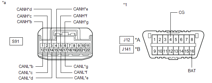
| *A | for DLC3 Connector Type A | *B | for DLC3 Connector Type B |
| *1 | DLC3 | - | - |
| *a | Front view of wire harness connector (to No. 11 CAN Junction Connector) | *b | to No. 8 CAN Junction Connector |
| *c | to Multiplex Tilt and Telescopic ECU | *d | to Main Body ECU (Multiplex Network Body ECU) |
| *e | to Position Control ECU and Switch Assembly LH (w/ Seat Position Memory System) | *f | to Multiplex Network Door ECU |
| *g | to Outer Mirror Control ECU Assembly (for Driver Side) | - | - |
Standard Resistance:
for DLC3 Connector Type A| Tester Connection | Condition | Specified Condition | Result | Connected to |
|---|---|---|---|---|
| *: w/ Seat Position Memory System | ||||
| S91-1 (CANH) - J12-4 (CG) | Cable disconnected from negative (-) battery terminal | 200 Ω or higher | Below 200 Ω: CANH short to ground | No. 8 CAN junction connector |
| S91-12 (CANL) - J12-4 (CG) | Cable disconnected from negative (-) battery terminal | 200 Ω or higher | Below 200 Ω: CANL short to ground | |
| S91-2 (CANH) - J12-4 (CG) | Cable disconnected from negative (-) battery terminal | 200 Ω or higher | Below 200 Ω: CANH short to ground | Multiplex tilt and telescopic ECU |
| S91-13 (CANL) - J12-4 (CG) | Cable disconnected from negative (-) battery terminal | 200 Ω or higher | Below 200 Ω: CANL short to ground | |
| S91-3 (CANH) - J12-4 (CG) | Cable disconnected from negative (-) battery terminal | 200 Ω or higher | Below 200 Ω: CANH short to ground | Main body ECU (Multiplex network body ECU) |
| S91-14 (CANL) - J12-4 (CG) | Cable disconnected from negative (-) battery terminal | 200 Ω or higher | Below 200 Ω: CANL short to ground | |
| S91-4 (CANH) - J12-4 (CG) | Cable disconnected from negative (-) battery terminal | 200 Ω or higher | Below 200 Ω: CANH short to ground | Position control ECU and switch assembly LH* |
| S91-15 (CANL) - J12-4 (CG) | Cable disconnected from negative (-) battery terminal | 200 Ω or higher | Below 200 Ω: CANL short to ground | |
| S91-5 (CANH) - J12-4 (CG) | Cable disconnected from negative (-) battery terminal | 200 Ω or higher | Below 200 Ω: CANH short to ground | Multiplex network door ECU |
| S91-16 (CANL) - J12-4 (CG) | Cable disconnected from negative (-) battery terminal | 200 Ω or higher | Below 200 Ω: CANL short to ground | |
| S91-6 (CANH) - J12-4 (CG) | Cable disconnected from negative (-) battery terminal | 200 Ω or higher | Below 200 Ω: CANH short to ground | Outer mirror control ECU assembly (for driver side) |
| S91-17 (CANL) - J12-4 (CG) | Cable disconnected from negative (-) battery terminal | 200 Ω or higher | Below 200 Ω: CANL short to ground | |
| S91-1 (CANH) - J12-16 (BAT) | Cable disconnected from negative (-) battery terminal | 6 kΩ or higher | Below 6 kΩ: CANH +B short | No. 8 CAN junction connector |
| S91-12 (CANL) - J12-16 (BAT) | Cable disconnected from negative (-) battery terminal | 6 kΩ or higher | Below 6 kΩ: CANL +B short | |
| S91-2 (CANH) - J12-16 (BAT) | Cable disconnected from negative (-) battery terminal | 6 kΩ or higher | Below 6 kΩ: CANH +B short | Multiplex tilt and telescopic ECU |
| S91-13 (CANL) - J12-16 (BAT) | Cable disconnected from negative (-) battery terminal | 6 kΩ or higher | Below 6 kΩ: CANL +B short | |
| S91-3 (CANH) - J12-16 (BAT) | Cable disconnected from negative (-) battery terminal | 6 kΩ or higher | Below 6 kΩ: CANH +B short | Main body ECU (Multiplex network body ECU) |
| S91-14 (CANL) - J12-16 (BAT) | Cable disconnected from negative (-) battery terminal | 6 kΩ or higher | Below 6 kΩ: CANL +B short | |
| S91-4 (CANH) - J12-16 (BAT) | Cable disconnected from negative (-) battery terminal | 6 kΩ or higher | Below 6 kΩ: CANH +B short | Position control ECU and switch assembly LH* |
| S91-15 (CANL) - J12-16 (BAT) | Cable disconnected from negative (-) battery terminal | 6 kΩ or higher | Below 6 kΩ: CANL +B short | |
| S91-5 (CANH) - J12-16 (BAT) | Cable disconnected from negative (-) battery terminal | 6 kΩ or higher | Below 6 kΩ: CANH +B short | Multiplex network door ECU |
| S91-16 (CANL) - J12-16 (BAT) | Cable disconnected from negative (-) battery terminal | 6 kΩ or higher | Below 6 kΩ: CANL +B short | |
| S91-6 (CANH) - J12-16 (BAT) | Cable disconnected from negative (-) battery terminal | 6 kΩ or higher | Below 6 kΩ: CANH +B short | Outer mirror control ECU assembly (for driver side) |
| S91-17 (CANL) - J12-16 (BAT) | Cable disconnected from negative (-) battery terminal | 6 kΩ or higher | Below 6 kΩ: CANL +B short | |
| Tester Connection | Condition | Specified Condition | Result | Connected to |
|---|---|---|---|---|
| *: w/ Seat Position Memory System | ||||
| S91-1 (CANH) - J141-4 (CG) | Cable disconnected from negative (-) battery terminal | 200 Ω or higher | Below 200 Ω: CANH short to ground | No. 8 CAN junction connector |
| S91-12 (CANL) - J141-4 (CG) | Cable disconnected from negative (-) battery terminal | 200 Ω or higher | Below 200 Ω: CANL short to ground | |
| S91-2 (CANH) - J141-4 (CG) | Cable disconnected from negative (-) battery terminal | 200 Ω or higher | Below 200 Ω: CANH short to ground | Multiplex tilt and telescopic ECU |
| S91-13 (CANL) - J141-4 (CG) | Cable disconnected from negative (-) battery terminal | 200 Ω or higher | Below 200 Ω: CANL short to ground | |
| S91-3 (CANH) - J141-4 (CG) | Cable disconnected from negative (-) battery terminal | 200 Ω or higher | Below 200 Ω: CANH short to ground | Main body ECU (Multiplex network body ECU) |
| S91-14 (CANL) - J141-4 (CG) | Cable disconnected from negative (-) battery terminal | 200 Ω or higher | Below 200 Ω: CANL short to ground | |
| S91-4 (CANH) - J141-4 (CG) | Cable disconnected from negative (-) battery terminal | 200 Ω or higher | Below 200 Ω: CANH short to ground | Position control ECU and switch assembly LH* |
| S91-15 (CANL) - J141-4 (CG) | Cable disconnected from negative (-) battery terminal | 200 Ω or higher | Below 200 Ω: CANL short to ground | |
| S91-5 (CANH) - J141-4 (CG) | Cable disconnected from negative (-) battery terminal | 200 Ω or higher | Below 200 Ω: CANH short to ground | Multiplex network door ECU |
| S91-16 (CANL) - J141-4 (CG) | Cable disconnected from negative (-) battery terminal | 200 Ω or higher | Below 200 Ω: CANL short to ground | |
| S91-6 (CANH) - J141-4 (CG) | Cable disconnected from negative (-) battery terminal | 200 Ω or higher | Below 200 Ω: CANH short to ground | Outer mirror control ECU assembly (for driver side) |
| S91-17 (CANL) - J141-4 (CG) | Cable disconnected from negative (-) battery terminal | 200 Ω or higher | Below 200 Ω: CANL short to ground | |
| S91-1 (CANH) - J141-16 (BAT) | Cable disconnected from negative (-) battery terminal | 6 kΩ or higher | Below 6 kΩ: CANH +B short | No. 8 CAN junction connector |
| S91-12 (CANL) - J141-16 (BAT) | Cable disconnected from negative (-) battery terminal | 6 kΩ or higher | Below 6 kΩ: CANL +B short | |
| S91-2 (CANH) - J141-16 (BAT) | Cable disconnected from negative (-) battery terminal | 6 kΩ or higher | Below 6 kΩ: CANH +B short | Multiplex tilt and telescopic ECU |
| S91-13 (CANL) - J141-16 (BAT) | Cable disconnected from negative (-) battery terminal | 6 kΩ or higher | Below 6 kΩ: CANL +B short | |
| S91-3 (CANH) - J141-16 (BAT) | Cable disconnected from negative (-) battery terminal | 6 kΩ or higher | Below 6 kΩ: CANH +B short | Main body ECU (Multiplex network body ECU) |
| S91-14 (CANL) - J141-16 (BAT) | Cable disconnected from negative (-) battery terminal | 6 kΩ or higher | Below 6 kΩ: CANL +B short | |
| S91-4 (CANH) - J141-16 (BAT) | Cable disconnected from negative (-) battery terminal | 6 kΩ or higher | Below 6 kΩ: CANH +B short | Position control ECU and switch assembly LH* |
| S91-15 (CANL) - J141-16 (BAT) | Cable disconnected from negative (-) battery terminal | 6 kΩ or higher | Below 6 kΩ: CANL +B short | |
| S91-5 (CANH) - J141-16 (BAT) | Cable disconnected from negative (-) battery terminal | 6 kΩ or higher | Below 6 kΩ: CANH +B short | Multiplex network door ECU |
| S91-16 (CANL) - J141-16 (BAT) | Cable disconnected from negative (-) battery terminal | 6 kΩ or higher | Below 6 kΩ: CANL +B short | |
| S91-6 (CANH) - J141-16 (BAT) | Cable disconnected from negative (-) battery terminal | 6 kΩ or higher | Below 6 kΩ: CANH +B short | Outer mirror control ECU assembly (for driver side) |
| S91-17 (CANL) - J141-16 (BAT) | Cable disconnected from negative (-) battery terminal | 6 kΩ or higher | Below 6 kΩ: CANL +B short | |
HINT:
- It is only necessary to perform the inspection in the above table for the result (short circuit) that was obtained in the Check Sub Bus 1 inspection.
- Find the necessary inspection from the Result column that matches the result in the Result column from the Check Sub Bus 1 inspection.
| Result | Proceed to |
|---|---|
| OK | A |
| NG (Main body ECU (multiplex network body ECU) main line) | B |
| NG (ECU or sensor branch line) | C |
| NG (No. 8 CAN junction connector main line) | D |
| A | | REPLACE NO. 11 CAN JUNCTION CONNECTOR |
| B | | REPAIR OR REPLACE CAN MAIN BUS LINE OR CONNECTOR (NO. 11 CAN JUNCTION CONNECTOR - MAIN BODY ECU (MULTIPLEX NETWORK BODY ECU)) |
| C | | GO TO STEP 22 |
|
| 21. | CHECK FOR SHORT IN SUB BUS 1 LINE (NO. 8 CAN JUNCTION CONNECTOR) |
(a) Reconnect the S91 No. 11 CAN junction connector.
(b) Disconnect the R55 No. 8 CAN junction connector.
(c) Measure the resistance according to the value(s) in the table below.
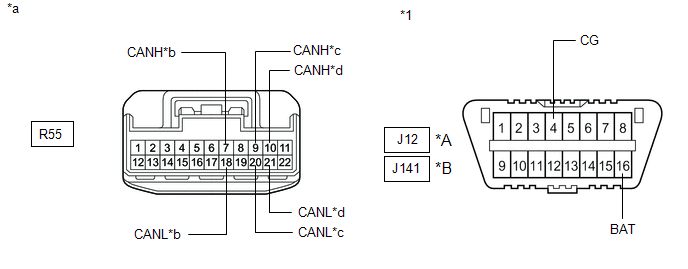
| *A | for DLC3 Connector Type A | *B | for DLC3 Connector Type B |
| *1 | DLC3 | - | - |
| *a | Front view of wire harness connector (to No. 8 CAN Junction Connector) | *b | to No. 11 CAN Junction Connector |
| *c | to No. 1 CAN Junction Terminal | *d | to Outer Mirror Control ECU Assembly (for Front Passenger Side) |
Standard Resistance:
for DLC3 Connector Type A| Tester Connection | Condition | Specified Condition | Result | Connected to |
|---|---|---|---|---|
| R55-7 (CANH) - J12-4 (CG) | Cable disconnected from negative (-) battery terminal | 200 Ω or higher | Below 200 Ω: CANH short to ground | No. 11 CAN junction connector |
| R55-18 (CANL) - J12-4 (CG) | Cable disconnected from negative (-) battery terminal | 200 Ω or higher | Below 200 Ω: CANL short to ground | |
| R55-9 (CANH) - J12-4 (CG) | Cable disconnected from negative (-) battery terminal | 200 Ω or higher | Below 200 Ω: CANH short to ground | No. 1 CAN junction terminal |
| R55-20 (CANL) - J12-4 (CG) | Cable disconnected from negative (-) battery terminal | 200 Ω or higher | Below 200 Ω: CANL short to ground | |
| R55-10 (CANH) - J12-4 (CG) | Cable disconnected from negative (-) battery terminal | 200 Ω or higher | Below 200 Ω: CANH short to ground | Outer mirror control ECU assembly (for front passenger side) |
| R55-21 (CANL) - J12-4 (CG) | Cable disconnected from negative (-) battery terminal | 200 Ω or higher | Below 200 Ω: CANL short to ground | |
| R55-7 (CANH) - J12-16 (BAT) | Cable disconnected from negative (-) battery terminal | 6 kΩ or higher | Below 6 kΩ: CANH +B short | No. 11 CAN junction connector |
| R55-18 (CANL) - J12-16 (BAT) | Cable disconnected from negative (-) battery terminal | 6 kΩ or higher | Below 6 kΩ: CANL +B short | |
| R55-9 (CANH) - J12-16 (BAT) | Cable disconnected from negative (-) battery terminal | 6 kΩ or higher | Below 6 kΩ: CANH +B short | No. 1 CAN junction terminal |
| R55-20 (CANL) - J12-16 (BAT) | Cable disconnected from negative (-) battery terminal | 6 kΩ or higher | Below 6 kΩ: CANL +B short | |
| R55-10 (CANH) - J12-16 (BAT) | Cable disconnected from negative (-) battery terminal | 6 kΩ or higher | Below 6 kΩ: CANH +B short | Outer mirror control ECU assembly (for front passenger side) |
| R55-21 (CANL) - J12-16 (BAT) | Cable disconnected from negative (-) battery terminal | 6 kΩ or higher | Below 6 kΩ: CANL +B short |
| Tester Connection | Condition | Specified Condition | Result | Connected to |
|---|---|---|---|---|
| R55-7 (CANH) - J141-4 (CG) | Cable disconnected from negative (-) battery terminal | 200 Ω or higher | Below 200 Ω: CANH short to ground | No. 11 CAN junction connector |
| R55-18 (CANL) - J141-4 (CG) | Cable disconnected from negative (-) battery terminal | 200 Ω or higher | Below 200 Ω: CANL short to ground | |
| R55-9 (CANH) - J141-4 (CG) | Cable disconnected from negative (-) battery terminal | 200 Ω or higher | Below 200 Ω: CANH short to ground | No. 1 CAN junction terminal |
| R55-20 (CANL) - J141-4 (CG) | Cable disconnected from negative (-) battery terminal | 200 Ω or higher | Below 200 Ω: CANL short to ground | |
| R55-10 (CANH) - J141-4 (CG) | Cable disconnected from negative (-) battery terminal | 200 Ω or higher | Below 200 Ω: CANH short to ground | Outer mirror control ECU assembly (for front passenger side) |
| R55-21 (CANL) - J141-4 (CG) | Cable disconnected from negative (-) battery terminal | 200 Ω or higher | Below 200 Ω: CANL short to ground | |
| R55-7 (CANH) - J141-16 (BAT) | Cable disconnected from negative (-) battery terminal | 6 kΩ or higher | Below 6 kΩ: CANH +B short | No. 11 CAN junction connector |
| R55-18 (CANL) - J141-16 (BAT) | Cable disconnected from negative (-) battery terminal | 6 kΩ or higher | Below 6 kΩ: CANL +B short | |
| R55-9 (CANH) - J141-16 (BAT) | Cable disconnected from negative (-) battery terminal | 6 kΩ or higher | Below 6 kΩ: CANH +B short | No. 1 CAN junction terminal |
| R55-20 (CANL) - J141-16 (BAT) | Cable disconnected from negative (-) battery terminal | 6 kΩ or higher | Below 6 kΩ: CANL +B short | |
| R55-10 (CANH) - J141-16 (BAT) | Cable disconnected from negative (-) battery terminal | 6 kΩ or higher | Below 6 kΩ: CANH +B short | Outer mirror control ECU assembly (for front passenger side) |
| R55-21 (CANL) - J141-16 (BAT) | Cable disconnected from negative (-) battery terminal | 6 kΩ or higher | Below 6 kΩ: CANL +B short |
HINT:
- It is only necessary to perform the inspection in the above table for the result (short circuit) that was obtained in the Check Sub Bus 1 inspection.
- Find the necessary inspection from the Result column that matches the result in the Result column from the Check Sub Bus 1 inspection.
| Result | Proceed to |
|---|---|
| OK | A |
| NG (No. 1 CAN junction terminal main line) | B |
| NG (ECU or sensor branch lines) | C |
| NG (No. 11 CAN junction connector main line) | D |
| A | | REPLACE NO. 8 CAN JUNCTION CONNECTOR |
| B | | REPAIR OR REPLACE CAN MAIN BUS LINE OR CONNECTOR (NO. 8 CAN JUNCTION CONNECTOR - NO. 1 CAN JUNCTION TERMINAL) |
| D | | REPAIR OR REPLACE CAN MAIN BUS LINE OR CONNECTOR (NO. 8 CAN JUNCTION CONNECTOR - NO. 11 CAN JUNCTION CONNECTOR) |
|
| 22. | CHECK FOR SHORT IN SUB BUS 1 LINE (ECU, SENSOR) |
(a) Reconnect all wire harness connectors.
(b) Disconnect the connector that includes terminals CANH and CANL from the ECU or sensor to which the bus line shorted to +B or shorted to GND is connected.
Click here
| (c) Measure the resistance according to the value(s) in the table below. Standard Resistance: for DLC3 Connector Type A
HINT:
|
|
| OK | | REPLACE CORRESPONDING ECU OR SENSOR |
| NG | | REPAIR OR REPLACE CORRESPONDING ECU OR SENSOR BRANCH LINE OR CONNECTOR |
 Lost Communication with Tilt & (U1115)
DESCRIPTION DTC No. Detection Item DTC Detection Condition Trouble Area Note U1115 Lost Communication with Tilt & Telescopic Module No communication from the multiplex tilt and ...
 Brake Actuator (Skid Control ECU) Communication Stop Mode
DESCRIPTION Detection Item Symptom Trouble Area Brake Actuator (Skid Control ECU) Communication Stop Mode Either condition is met:
"Skid Control (ABS/VSC/TRAC)" is not displayed on the ...
Other materials:
Lexus RX (RX 350L, RX450h) 2016-2026 Repair Manual > Front Power Seat Control System (w/ Memory): Parts Location
PARTS LOCATION ILLUSTRATION *1 FRONT DOOR COURTESY LIGHT SWITCH ASSEMBLY (DRIVER DOOR) *2 FRONT SEAT OUTER BELT ASSEMBLY LH *3 SEAT MEMORY SWITCH LH *4 OUTER MIRROR CONTROL ECU ASSEMBLY (DRIVER DOOR) *5 ECM *6 MULTIPLEX NETWORK MASTER SWITCH ASSEMBLY - DOOR CONTROL SWIT ...
Lexus RX (RX 350L, RX450h) 2016-2026 Repair Manual > Generator (for 150 A Type): Installation
INSTALLATION PROCEDURE 1. INSTALL GENERATOR ASSEMBLY (a) Install the wire harness clamp bracket with the bolt. Torque: 8.4 N·m {86 kgf·cm, 74 in·lbf} (b) Type A: (1) Install the generator assembly with the 2 bolts. Torque: 43 N·m {438 kgf·cm, 32 ft·lbf} (2) Temporarily install the generator ...
Lexus RX (RX 350L, RX450h) 2016-{YEAR} Owners Manual
- For your information
- Pictorial index
- For safety and security
- Instrument cluster
- Operation of each component
- Driving
- Lexus Display Audio system
- Interior features
- Maintenance and care
- When trouble arises
- Vehicle specifications
- For owners
Lexus RX (RX 350L, RX450h) 2016-{YEAR} Repair Manual

0.0143