Lexus RX (RX 350L, RX450h) 2016-2026 Repair Manual: Check Bus 3 Line for Short to GND
DESCRIPTION
There may be a short circuit between one of the CAN bus lines and GND when there is no resistance between terminal 6 (CA3H) of the network gateway ECU and terminal 4 (CG) of the DLC3, or terminal 21 (CA3L) of the network gateway ECU and terminal 4 (CG) of the DLC3.
| Symptom | Trouble Area |
|---|---|
| There is no resistance between terminal 6 (CA3H) of the network gateway ECU and terminal 4 (CG) of the DLC3, or terminal 21 (CA3L) of the network gateway ECU and terminal 4 (CG) of the DLC3. |
|
WIRING DIAGRAM
.png)
CAUTION / NOTICE / HINT
CAUTION:
When performing the confirmation driving pattern, obey all speed limits and traffic laws.
NOTICE:
- Before measuring the resistance of the CAN bus, turn the engine switch off and leave the vehicle for 1 minute or more without operating the key or any switches, or opening or closing the doors. After that, disconnect the cable from the negative (-) battery terminal and leave the vehicle for 1 minute or more before measuring the resistance.
-
After turning the engine switch off, waiting time may be required before disconnecting the cable from the negative (-) battery terminal. Therefore, make sure to read the disconnecting the cable from the negative (-) battery terminal notices before proceeding with work.
Click here
.gif)
-
Because the order of diagnosis is important to allow correct diagnosis, make sure to begin troubleshooting using How to Proceed with Troubleshooting when CAN communication system related DTCs are output.
Click here
-
After performing repairs, perform the DTC check procedure and confirm that the DTCs are not output again.
DTC check procedure: Turn the engine switch on (IG) and wait for 1 minute or more. Then operate the suspected malfunctioning system and drive the vehicle at 60 km/h (37 mph) or more for 5 minutes or more.
-
After the repair, perform the CAN bus check and check that all the ECUs and sensors connected to the CAN communication system are displayed.
Click here
HINT:
- Operating the engine switch, any other switches or a door triggers related ECU and sensor communication on the CAN. This communication will cause the resistance value to change.
- Even after DTCs are cleared, if a DTC is stored again after driving the vehicle for a while, the malfunction may be occurring due to vibration of the vehicle. In such a case, wiggling the ECUs or wire harness while performing the inspection below may help determine the cause of the malfunction.
PROCEDURE
| 1. | CHECK FOR SHORT TO GND IN CAN BUS LINE (NETWORK GATEWAY ECU) |
(a) Disconnect the cable from the negative (-) battery terminal.
(b) Disconnect the J75 network gateway ECU connector.
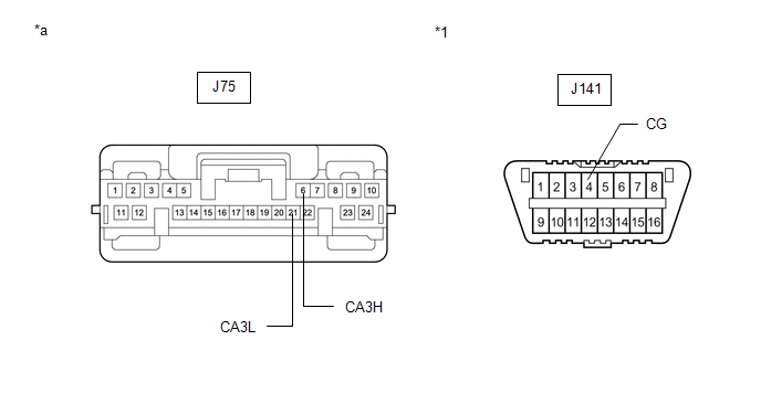
| *1 | DLC3 | - | - |
| *a | Front view of wire harness connector (to Network Gateway ECU) | - | - |
(c) Measure the resistance according to the value(s) in the table below.
Standard Resistance:
| Tester Connection | Condition | Specified Condition |
|---|---|---|
| J75-6 (CA3H) - J141-4 (CG) | Cable disconnected from negative (-) battery terminal | 200 Ω or higher |
| J75-21 (CA3L) - J141-4 (CG) |
| OK | .gif) | REPLACE NETWORK GATEWAY ECU |
|
.gif)
| 2. | CHECK FOR SHORT TO GND IN CAN BUS LINE (NO. 6 CAN JUNCTION CONNECTOR) |
(a) Reconnect the J75 network gateway ECU connector.
(b) Disconnect the J98 No. 6 CAN junction connector.
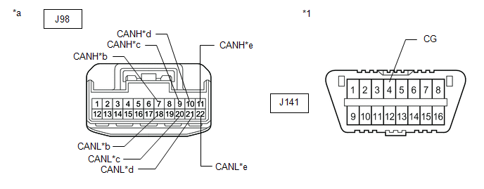
| *1 | DLC3 | - | - |
| *a | Front view of wire harness connector (to No. 6 CAN Junction Connector) | *b | to Network Gateway ECU |
| *c | to DCM (Telematics Transceiver) (w/ Manual (SOS) Switch) | *d | to Radio Receiver Assembly |
| *e | to Network Gateway ECU | - | - |
(c) Measure the resistance according to the value(s) in the table below.
Standard Resistance:
| Tester Connection | Condition | Specified Condition | Connected to |
|---|---|---|---|
| J98-7 (CANH) - J141-4 (CG) | Cable disconnected from negative (-) battery terminal | 200 Ω or higher | Network gateway ECU |
| J98-18 (CANL) - J141-4 (CG) | |||
| J98-9 (CANH) - J141-4 (CG) | Cable disconnected from negative (-) battery terminal | 200 Ω or higher | DCM (telematics transceiver)* |
| J98-20 (CANL) - J141-4 (CG) | |||
| J98-10 (CANH) - J141-4 (CG) | Cable disconnected from negative (-) battery terminal | 200 Ω or higher | Radio receiver assembly |
| J98-21 (CANL) - J141-4 (CG) | |||
| J98-11 (CANH) - J141-4 (CG) | Cable disconnected from negative (-) battery terminal | 200 Ω or higher | Network gateway ECU |
| J98-22 (CANL) - J141-4 (CG) |
- *: w/ Manual (SOS) Switch
| Result | Proceed to |
|---|---|
| OK | A |
| NG (Network gateway ECU main line) | B |
| NG (ECU or sensor bus line) | C |
| A | | REPLACE NO. 6 CAN JUNCTION CONNECTOR |
| B | | REPAIR OR REPLACE CAN MAIN BUS LINE OR CONNECTOR (NO. 6 CAN JUNCTION CONNECTOR - NETWORK GATEWAY ECU) |
|
| 3. | CHECK FOR SHORT TO GND IN CAN BUS LINE (ECU, SENSOR) |
(a) Reconnect all wire harness connectors.
(b) Disconnect the connector that includes terminals CANH and CANL from the ECU or sensor to which the bus line shorted to GND is connected.
Click here
(c) Measure the resistance according to the value(s) in the table below.
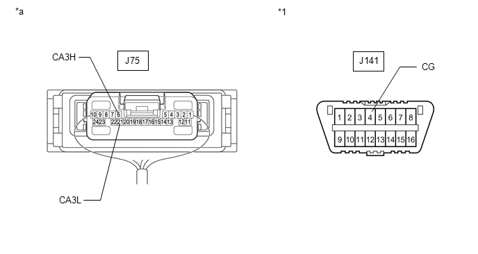
| *1 | DLC3 | - | - |
| *a | Component with harness connected (Network Gateway ECU) | - | - |
Standard Resistance:
| Tester Connection | Condition | Specified Condition |
|---|---|---|
| J75-6 (CA3H) - J141-4 (CG) | Cable disconnected from negative (-) battery terminal | 200 Ω or higher |
| J75-21 (CA3L) - J141-4 (CG) |
HINT:
If the resistance changes to 200 Ω or higher when the connector is disconnected from the ECU or sensor, there may be a short in the ECU or sensor.
| OK | | REPLACE CORRESPONDING ECU OR SENSOR |
| NG | | REPAIR OR REPLACE CORRESPONDING ECU OR SENSOR CAN BUS LINE OR CONNECTOR |
 Check Bus 3 Line for Short to +B
DESCRIPTION There may be a short circuit between one of the CAN bus lines and +B when there is no resistance between terminal 6 (CA3H) of the network gateway ECU and terminal 16 (BAT) of the DLC3, or ...
 Open in One Side of Bus 3 Branch Line
DESCRIPTION If an ECU or sensor is not displayed on the CAN Bus Check screen of the Techstream and some ECUs and sensors repeatedly appear and disappear from the screen when the CAN main bus lines are ...
Other materials:
Lexus RX (RX 350L, RX450h) 2016-2026 Repair Manual > Audio And Visual System (for 8 Inch Display): Customize Parameters
CUSTOMIZE PARAMETERS CUSTOMIZING WITH REMOTE TOUCH (a) Customizing with the touch function cancellation function. NOTICE: Confirm the touchpad surface is free of foreign matter before customizing. (1) Turn the engine switch on (ACC). (2) Simultaneously press and hold the "HOME" switch and back switc ...
Lexus RX (RX 350L, RX450h) 2016-2026 Repair Manual > Can Communication System: Problem Symptoms Table
PROBLEM SYMPTOMS TABLE HINT:
Use the table below to help determine the cause of problem symptoms. If multiple suspected areas are listed, the potential causes of the symptoms are listed in order of probability in the "Suspected Area" column of the table. Check each symptom by checking the suspect ...
Lexus RX (RX 350L, RX450h) 2016-{YEAR} Owners Manual
- For your information
- Pictorial index
- For safety and security
- Instrument cluster
- Operation of each component
- Driving
- Lexus Display Audio system
- Interior features
- Maintenance and care
- When trouble arises
- Vehicle specifications
- For owners
Lexus RX (RX 350L, RX450h) 2016-{YEAR} Repair Manual

0.01