Lexus RX (RX 350L, RX450h) 2016-2026 Repair Manual: Installation
INSTALLATION
CAUTION / NOTICE / HINT
NOTICE:
-
Before replacing the main body ECU (multiplex network body ECU), refer to Registration.
Click here
.gif)
- After the main body ECU (multiplex network body ECU) has been replaced, the automatic light control system will not operate until the engine is started.
PROCEDURE
1. INSTALL MAIN BODY ECU (MULTIPLEX NETWORK BODY ECU)
NOTICE:
- Make sure that the connecting surfaces are free of foreign matter.
- Do not touch the main body ECU (multiplex network body ECU) connector.
(a) Set the main body ECU (multiplex network body ECU) to the position where the guide of the main body ECU (multiplex network body ECU) contacts the housing sidewall of the instrument panel junction block assembly as shown in the illustration.
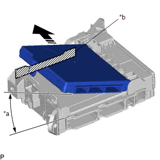
| *a | 20°or more |
| *b | Housing Sidewall |
.png) | Set in this Direction |
HINT:
Make sure to keep the angle at 20° or more as shown in the illustration.
(b) Slide the main body ECU (multiplex network body ECU) along the housing sidewall as shown in the illustration and engage the 2 guides.
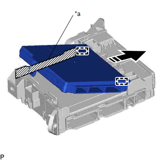
| *a | Housing Sidewall |
| | Slide in this Direction |
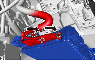
(c) While keeping the main body ECU (multiplex network body ECU) in contact with side A of the instrument panel junction block assembly (axis of rotation), lower it as shown in the illustration.
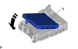
| *a | Side A |
| | Install in this Direction |
(d) Press the push area until the claw engages to install the main body ECU (multiplex network body ECU).
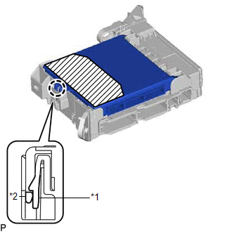
| *1 | Instrument Panel Junction Block Assembly |
| *2 | Main Body ECU (Multiplex Network Body ECU) |
.png) | Push Area |
NOTICE:
- Make sure to press only the push area.
- Confirm the engagement of the main body ECU (multiplex network body ECU) and instrument panel junction block assembly by listening for the click sound of the lock engaging.
HINT:
If a click sound cannot be heard, visually check the engagement of the lock. The engagement can also be confirmed if the main body ECU (multiplex network body ECU) and instrument panel junction block assembly are flush.
2. INSTALL INSTRUMENT PANEL JUNCTION BLOCK ASSEMBLY WITH MAIN BODY ECU
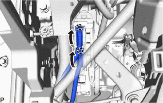
(a) Connect the 2 connectors and push down the 2 lock levers to engage the 2 claws and lock the connector as shown in the illustration.
| | Install in this Direction |
NOTICE:
Be sure to connect the connector securely.
(b) Engage the clamp.
(c) Install the instrument panel junction block assembly with main body ECU with the 2 nuts.
Torque:
8.0 N·m {82 kgf·cm, 71 in·lbf}
(d) Connect the 2 connectors and raise the 2 lock levers to engage the 2 claws and lock the connector as shown in the illustration.
| | Install in this Direction |
NOTICE:
Be sure to connect the connector securely.
(e) Connect each connector.
3. INSTALL LOWER INSTRUMENT PANEL FINISH PANEL SUB-ASSEMBLY
Click here
4. CONNECT HOOD LOCK CONTROL LEVER SUB-ASSEMBLY
Click here
5. INSTALL NO. 1 INSTRUMENT PANEL UNDER COVER SUB-ASSEMBLY
Click here
6. INSTALL COWL SIDE TRIM BOARD LH
Click here
7. INSTALL FRONT DOOR SCUFF PLATE LH
Click here
8. INSTALL INSTRUMENT PANEL GARNISH LH
Click here
9. CONNECT CABLE TO NEGATIVE BATTERY TERMINAL
NOTICE:
When disconnecting the cable, some systems need to be initialized after the cable is reconnected.
Click here
 Components
COMPONENTS ILLUSTRATION *1 COWL SIDE TRIM BOARD LH *2 FRONT DOOR SCUFF PLATE LH *3 HOOD LOCK CONTROL LEVER SUB-ASSEMBLY *4 INSTRUMENT PANEL GARNISH LH *5 INSTRUMENT PANEL JUN ...
 Removal
REMOVAL CAUTION / NOTICE / HINT The necessary procedures (adjustment, calibration, initialization, or registration) that must be performed after parts are removed and installed, or replaced during mai ...
Other materials:
Lexus RX (RX 350L, RX450h) 2016-2026 Repair Manual > Noise Filter (w/ Rear No. 2 Seat): On-vehicle Inspection
ON-VEHICLE INSPECTION PROCEDURE 1. INSPECT RADIO SETTING CONDENSER (a) With the radio setting condenser installed, check that there is no looseness or other abnormalities. (b) Measure the resistance of the radio setting condenser according to the value(s) in the table below. Standard Resistance: ...
Lexus RX (RX 350L, RX450h) 2016-2026 Repair Manual > Lighting System (w/ Automatic Headlight Beam Level Control System): Variation Code not Written (B2451)
DESCRIPTION The No. 1 headlight ECU sub-assembly LH stores this DTC if the vehicle specifications have not been stored. DTC No. Detection Item DTC Detection Condition Trouble Area DTC Output from B2451 Variation Code not Written
The engine switch is on (IG).
Vehicle speci ...
Lexus RX (RX 350L, RX450h) 2016-{YEAR} Owners Manual
- For your information
- Pictorial index
- For safety and security
- Instrument cluster
- Operation of each component
- Driving
- Lexus Display Audio system
- Interior features
- Maintenance and care
- When trouble arises
- Vehicle specifications
- For owners
Lexus RX (RX 350L, RX450h) 2016-{YEAR} Repair Manual

0.0119