Lexus RX (RX 350L, RX450h) 2016-2026 Repair Manual: Tilt Position Sensor or Tilt Motor Circuit Malfunction (B2610)
DESCRIPTION
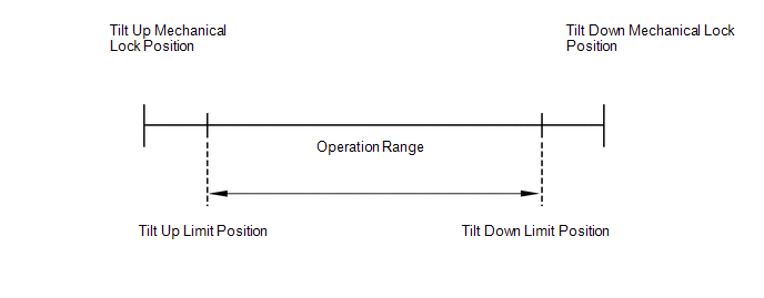
The tilt motor is operated by the power source voltage supplied from the multiplex tilt and telescopic ECU and tilts the steering column up and down. The tilt position sensor (Hall IC) in the tilt motor detects the tilt angle of the steering column and sends a signal to the multiplex tilt and telescopic ECU based on that angle.
HINT:
Limit positions can be confirmed on the Techstream.
| DTC No. | Detection Item | DTC Detection Condition | Trouble Area |
|---|---|---|---|
| B2610 | Tilt Position Sensor or Tilt Motor Circuit Malfunction | Tilt operation stops within the operation range while operating. |
|
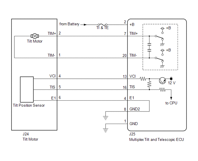
WIRING DIAGRAM
CAUTION / NOTICE / HINT
NOTICE:
If the electric power steering column sub-assembly (tilt steering gear assembly w/ motor) has been replaced, perform torque sensor zero point calibration.
Click here .gif)
HINT:
Inspect the fuses for circuits related to this system before performing the following inspection procedure.
PROCEDURE
| 1. | PERFORM ACTIVE TEST USING TECHSTREAM (TILT OPERATION) |
| (a) Turn the engine switch off. |
|
(b) Connect the Techstream to the DLC3.
(c) Turn the engine switch on (IG).
(d) Turn the Techstream on.
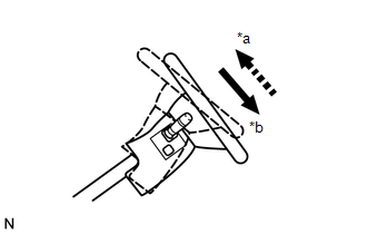
(e) Check that the steering wheel tilts up and down.
(f) Enter the following menus: Body Electrical / Tilt & Telescopic / Active Test.
Body Electrical > Tilt&Telescopic > Active Test| Tester Display | Measurement Item | Control Range | Diagnostic Note |
|---|---|---|---|
| Tilt Operation | Tilt operation | UP/DOWN | - |
| Tester Display |
|---|
| Tilt Operation |
OK:
The steering wheel tilts up and down.
| NG | .gif) | GO TO STEP 6 |
|
.gif)
| 2. | CHECK HARNESS AND CONNECTOR (MULTIPLEX TILT AND TELESCOPIC ECU - TILT POSITION SENSOR) |
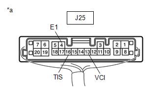
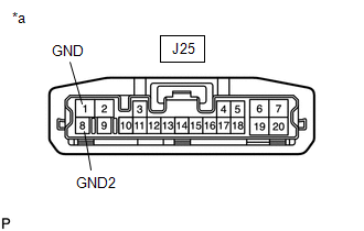
(a) Disconnect the J25 multiplex tilt and telescopic ECU connector.
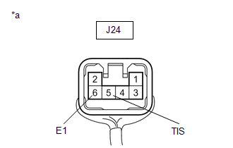
(b) Disconnect the J24 tilt motor connector.
(c) Measure the resistance according to the value(s) in the table below.
Standard Resistance:
| Tester Connection | Condition | Specified Condition |
|---|---|---|
| J25-13 (VCI) - J24-4 (VCI) | Always | Below 1 Ω |
| J25-16 (TIS) - J24-5 (TIS) | Always | Below 1 Ω |
| J25-4 (E1) -J24-6 (E1) | Always | Below 1 Ω |
| J25-13 (VCI) or J24-4 (VCI) - Body ground | Always | 10 kΩ or higher |
| J25-16 (TIS) or J24-5 (TIS) - Body ground | Always | 10 kΩ or higher |
| J25-4 (E1) or J24-6 (E1) - Body ground | Always | 10 kΩ or higher |
| NG | | REPAIR OR REPLACE HARNESS OR CONNECTOR |
|
| 3. | CHECK HARNESS AND CONNECTOR (MULTIPLEX TILT AND TELESCOPIC ECU - BODY GROUND) |
| (a) Disconnect the J25 multiplex tilt and telescopic ECU connector. |
|

(b) Measure the resistance according to the value(s) in the table below.
Standard Resistance:
| Tester Connection | Condition | Specified Condition |
|---|---|---|
| J25-1 (GND) - Body ground | Always | Below 1 Ω |
| J25-8 (GND2) - Body ground | Always | Below 1 Ω |
| NG | | REPAIR OR REPLACE HARNESS OR CONNECTOR |
|
| 4. | CHECK MULTIPLEX TILT AND TELESCOPIC ECU (VCI, TIS TERMINAL VOLTAGE) |
| (a) Disconnect the J24 tilt motor connector. |
|
(b) Reconnect the J25 multiplex tilt and telescopic ECU connector.
(c) Measure the voltage according to the value(s) in the table below.
Standard Voltage:
| Tester Connection | Condition | Specified Condition |
|---|---|---|
| J25-13 (VCI) - J25-4 (E1) | Engine switch on (IG) | 8 to 14 V |
| J25-16 (TIS) - J25-4 (E1) | Engine switch on (IG) | 8 to 14 V |
| NG | | REPLACE MULTIPLEX TILT AND TELESCOPIC ECU |
|
| 5. | CHECK TILT POSITION SENSOR |
| (a) Reconnect the J25 multiplex tilt and telescopic ECU connector. |
|
(b) Reconnect the J24 tilt motor connector.
(c) Measure the voltage according to the value(s) in the table below.
Standard Voltage:
| Tester Connection | Condition | Specified Condition |
|---|---|---|
| J24-5 (TIS) - J24-6 (E1) | Steering wheel tilting up or tilting down | Pulse generation High: 8 to 14 V Low: Below 1 V |
| OK | | REPLACE MULTIPLEX TILT AND TELESCOPIC ECU |
| NG | | REPLACE ELECTRIC POWER STEERING COLUMN SUB-ASSEMBLY (TILT STEERING GEAR ASSEMBLY W/ MOTOR) |
| 6. | CHECK HARNESS AND CONNECTOR (MULTIPLEX TILT AND TELESCOPIC ECU - BATTERY) |
| (a) Disconnect the J25 multiplex tilt and telescopic ECU connector. |
|
.png)
(b) Measure the voltage according to the value(s) in the table below.
Standard Voltage:
| Tester Connection | Condition | Specified Condition |
|---|---|---|
| J25-2 (+B) - Body ground | Always | 11 to 14 V |
| NG | | REPAIR OR REPLACE HARNESS OR CONNECTOR |
|
| 7. | CHECK HARNESS AND CONNECTOR (MULTIPLEX TILT AND TELESCOPIC ECU - BODY GROUND) |
| (a) Disconnect the J25 multiplex tilt and telescopic ECU connector. |
|
(b) Measure the resistance according to the value(s) in the table below.
Standard Resistance:
| Tester Connection | Condition | Specified Condition |
|---|---|---|
| J25-1 (GND) - Body ground | Always | Below 1 Ω |
| J25-8 (GND2) - Body ground | Always | Below 1 Ω |
| NG | | REPAIR OR REPLACE HARNESS OR CONNECTOR |
|
| 8. | CHECK HARNESS AND CONNECTOR (MULTIPLEX TILT AND TELESCOPIC ECU - TILT MOTOR) |
(a) Disconnect the J25 multiplex tilt and telescopic ECU connector.
(b) Disconnect the J24 tilt motor connector.
(c) Measure the resistance according to the value(s) in the table below.
Standard Resistance:
| Tester Connection | Condition | Specified Condition |
|---|---|---|
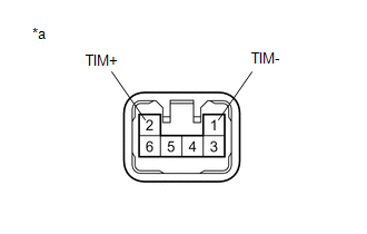
| J25-7 (TIM+) - J24-2 (TIM+) | Always | Below 1 Ω |
| J25-20 (TIM-) - J24-1 (TIM-) | Always | Below 1 Ω |
| J25-7 (TIM+) or J24-2 (TIM+) - Body ground | Always | 10 kΩ or higher |
| J25-20 (TIM-) or J24-1 (TIM-) - Body ground | Always | 10 kΩ or higher |
| NG | | REPAIR OR REPLACE HARNESS OR CONNECTOR |
|
| 9. | CHECK TILT MOTOR |
| (a) Apply 12 V battery voltage to the tilt motor connector. Then check the steering wheel tilt operation. OK:
|
|
| OK | | REPLACE MULTIPLEX TILT AND TELESCOPIC ECU |
| NG | | REPLACE ELECTRIC POWER STEERING COLUMN SUB-ASSEMBLY (TILT STEERING GEAR ASSEMBLY W/ MOTOR) |
 Tilt and Telescopic Manual Switch Circuit Malfunction (B2603)
DESCRIPTION Different voltage values are sent to the multiplex tilt and telescopic ECU by operating the tilt and telescopic switch. The multiplex tilt and telescopic ECU then judges which motor and in ...
 Telescopic Position Sensor or Telescopic Motor Circuit Malfunction (B2611)
DESCRIPTION The telescopic motor is operated by the power source voltage supplied from the multiplex tilt and telescopic ECU and slides the steering column forward and backward. The telescopic positio ...
Other materials:
Lexus RX (RX 350L, RX450h) 2016-2026 Repair Manual > Camshaft Oil Control Solenoid (for Bank 2): Removal
REMOVAL CAUTION / NOTICE / HINT The necessary procedures (adjustment, calibration, initialization or registration) that must be performed after parts are removed and installed, or replaced during camshaft timing oil control solenoid assembly removal/installation are shown below. Necessary Procedures ...
Lexus RX (RX 350L, RX450h) 2016-2026 Repair Manual > Sliding Roof System: Initialization
INITIALIZATION INITIALIZE SLIDING ROOF SYSTEM NOTICE:
When the sliding roof glass sub-assembly or sliding roof drive cable sub-assembly is adjusted or removed/installed, or the sliding roof drive gear sub-assembly is replaced, the sliding roof ECU (sliding roof drive gear sub-assembly) must be in ...
Lexus RX (RX 350L, RX450h) 2016-{YEAR} Owners Manual
- For your information
- Pictorial index
- For safety and security
- Instrument cluster
- Operation of each component
- Driving
- Lexus Display Audio system
- Interior features
- Maintenance and care
- When trouble arises
- Vehicle specifications
- For owners
Lexus RX (RX 350L, RX450h) 2016-{YEAR} Repair Manual

0.0106