Lexus RX (RX 350L, RX450h) 2016-2026 Repair Manual: Power Back Door cannot be Operated Using Kick Sensor
DESCRIPTION
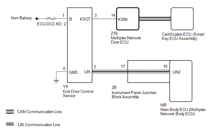
The kick door control sensor turns the sensing circuit on or off based on the vehicle speed and IG and ACC signals sent from the main body ECU (multiplex network body ECU) via LIN communication.
When the kick door control sensor detects a kick operation, it sends an operation signal to the multiplex network door ECU.
WIRING DIAGRAM
CAUTION / NOTICE / HINT
NOTICE:
-
Before troubleshooting, make sure that the "Kick Sensor Function" customize setting is set to "ON" (The default is "ON").
Click here
.gif)
-
The power back door system uses the CAN communication system. Inspect the communication function by following How to Proceed with Troubleshooting. Troubleshoot the power back door system after confirming that the CAN communication system is functioning properly.
Click here
-
Check the smart access system (for Entry Function) first before troubleshooting the power back door system.
Click here
-
Before troubleshooting, be sure to read Precautions for Hands Free Power Back Door.
Click here
-
If the multiplex network door ECU has been removed and installed or replaced, or if any of the connectors have been disconnected, initialize the power back door system.
Click here
-
After performing work, using the Techstream, read the Data List item "Kick Sensor Connection" and check that the kick door control sensor is connected.
Click here
- Inspect the fuses for circuits related to this system before performing the following procedure.
PROCEDURE
| 1. | CHECK FOR DTC |
(a) Connect the Techstream to the DLC3.
(b) Turn the engine switch on (IG).
(c) Turn the Techstream on.
(d) Enter the following menus: Body Electrical / Back Door / Trouble Codes.
(e) Check for DTCs.
Body Electrical > Back Door > Trouble CodesOK:
DTC is not output.
| NG | .gif) | GO TO DIAGNOSTIC TROUBLE CODE CHART |
|
.gif)
| 2. | READ VALUE USING TECHSTREAM |
(a) Enter the following menus: Body Electrical / Back Door / Data List.
(b) Read the Data List according to the display on the Techstream.
Body Electrical > Back Door > Data List| Tester Display | Measurement Item | Range | Normal Condition | Diagnostic Note |
|---|---|---|---|---|
| Kick Sensor Error | Status of the kick door control sensor error | Normal or Error | Normal: Kick door control sensor is normal Error: Kick door control sensor is abnormal | - |
| Tester Display |
|---|
| Kick Sensor Error |
OK:
On the display, Normal is displayed.
| NG | | REPLACE KICK DOOR CONTROL SENSOR |
|
| 3. | READ VALUE USING TECHSTREAM |
(a) Enter the following menus: Body Electrical / Back Door / Data List.
(b) Read the Data List according to the display on the Techstream.
Body Electrical > Back Door > Data List| Tester Display | Measurement Item | Range | Normal Condition | Diagnostic Note |
|---|---|---|---|---|
| Kick Sensor Detection | Status of the kick door control sensor detection | OFF or ON | OFF: Kick door control sensor not detecting a foot ON: Kick door control sensor detecting a foot | - |
| Tester Display |
|---|
| Kick Sensor Detection |
OK:
The display is as specified in the normal condition column.
| NG | | GO TO STEP 5 |
|
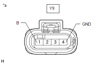
| 4. | CHECK HARNESS AND CONNECTOR (KICK DOOR CONTROL SENSOR - INSTRUMENT PANEL JUNCTION BLOCK ASSEMBLY) |
(a) Disconnect the Y9 kick door control sensor connector.
(b) Disconnect the 2B instrument panel junction block assembly connector.
(c) Measure the resistance according to the value(s) in the table below.
Standard Resistance:
| Tester Connection | Condition | Specified Condition |
|---|---|---|
| Y9-2 (LIN) - 2B-17 | Always | Below 1 Ω |
| OK | | REPLACE KICK DOOR CONTROL SENSOR |
| NG | | REPAIR OR REPLACE HARNESS OR CONNECTOR |
| 5. | CHECK HARNESS AND CONNECTOR (KICK DOOR CONTROL SENSOR - BATTERY AND BODY GROUND) |
| (a) Disconnect the Y9 kick door control sensor connector. |
|
(b) Measure the resistance according to the value(s) in the table below.
Standard Resistance:
| Tester Connection | Condition | Specified Condition |
|---|---|---|
| Y9-4 (GND) - Body ground | Always | Below 1 Ω |
(c) Measure the voltage according to the value(s) in the table below.
Standard Voltage:
| Tester Connection | Condition | Specified Condition |
|---|---|---|
| Y9-1 (B) - Body ground | Always | 11 to 14 V |
| NG | | REPAIR OR REPLACE HARNESS OR CONNECTOR |
|
| 6. | CHECK HARNESS AND CONNECTOR (KICK DOOR CONTROL SENSOR - MULTIPLEX NETWORK DOOR ECU) |
(a) Disconnect the Z16 multiplex network door ECU connector.
(b) Measure the resistance according to the value(s) in the table below.
Standard Resistance:
| Tester Connection | Condition | Specified Condition |
|---|---|---|
| Y9-3 (KSOT) - Z16-14 (KSIN) | Always | Below 1 Ω |
| Y9-3 (KSOT) or Z16-14 (KSIN) - Body ground | Always | 10 kΩ or higher |
| NG | | REPAIR OR REPLACE HARNESS OR CONNECTOR |
|
| 7. | CHECK MULTIPLEX NETWORK DOOR ECU |
(a) Remove the multiplex network door ECU with the connector(s) still connected.
Click here
| (b) Check the signal waveform according to the condition(s) in the table below. Measurement Condition
OK: The waveform displayed is as shown in the illustration. |
|
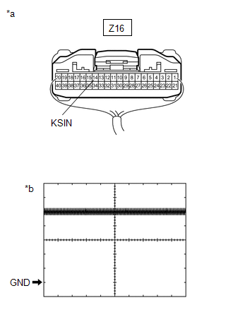
| OK | | REPLACE KICK DOOR CONTROL SENSOR |
| NG | | REPLACE MULTIPLEX NETWORK DOOR ECU |
 Jam Protection Function Activates During Power Back Door Operation
DESCRIPTION If the jam protection function activates during power back door operation, one of the following may be the cause: 1) improper fit of back door or a foreign object stuck in the back door, 2 ...
 Lock Function does not Operate (Close &)
DESCRIPTION The door control switch signal is sent to the multiplex network door ECU. If the power back door system does not operate when the door control switch is operated, the door control switch c ...
Other materials:
Lexus RX (RX 350L, RX450h) 2016-2026 Repair Manual > Noise Filter (w/ Rear No. 2 Seat): Removal
REMOVAL PROCEDURE 1. REMOVE REAR NO. 2 SEAT ASSEMBLY Click here 2. REMOVE REAR DOOR SCUFF PLATE LH Click here 3. REMOVE REAR DOOR INSIDE SCUFF PLATE LH Click here 4. REMOVE REAR SEAT OUTER TRACK BRACKET COVER LH for 60/40 Split Seat Type: Click here for Captain Seat Type: Click here 5. ...
Lexus RX (RX 350L, RX450h) 2016-2026 Repair Manual > Vehicle Stability Control System: Parts Location
PARTS LOCATION ILLUSTRATION *A w/o AVS *B for 2WD *C for AWD - - *1 FRONT SPEED SENSOR RH *2 FRONT SPEED SENSOR LH *3 FRONT AXLE HUB SUB-ASSEMBLY RH - FRONT SPEED SENSOR ROTOR RH *4 FRONT AXLE HUB SUB-ASSEMBLY LH - FRONT SPEED SENSOR ROTOR LH *5 REAR SKI ...
Lexus RX (RX 350L, RX450h) 2016-{YEAR} Owners Manual
- For your information
- Pictorial index
- For safety and security
- Instrument cluster
- Operation of each component
- Driving
- Lexus Display Audio system
- Interior features
- Maintenance and care
- When trouble arises
- Vehicle specifications
- For owners
Lexus RX (RX 350L, RX450h) 2016-{YEAR} Repair Manual

0.0095