Lexus RX (RX 350L, RX450h) 2016-2026 Repair Manual: Reassembly
REASSEMBLY
PROCEDURE
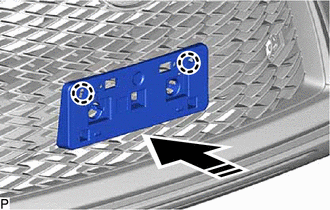
1. INSTALL FRONT BUMPER SIDE RETAINER LH
(a) Engage the claw as shown in the illustration.
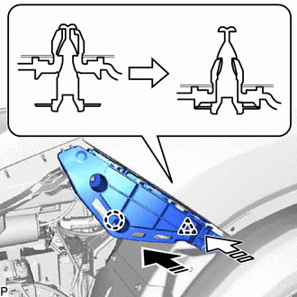
.png) | Install in this Direction (1) |
.png) | Install in this Direction (2) |
(b) Engage the clip as shown in the illustration.
| (c) Install the front bumper side retainer LH with the bolt. Torque: 5.4 N·m {55 kgf·cm, 48 in·lbf} |
|
.png)
2. INSTALL FRONT BUMPER SIDE RETAINER RH
HINT:
Use the same procedure as for the LH side.
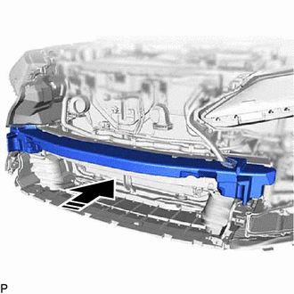
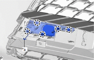
3. INSTALL FRONT BUMPER REINFORCEMENT SUB-ASSEMBLY
| (a) Install the front bumper reinforcement sub-assembly with the 6 bolts. Torque: 35 N·m {357 kgf·cm, 26 ft·lbf} |
|
.png)
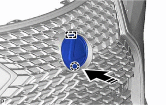
| (b) Install the 2 clips. |
|
.png)
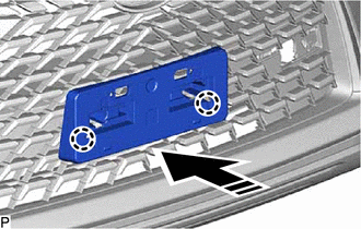
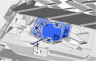
| (c) Engage the 3 clamps. |
|
.png)
4. INSTALL FRONT BUMPER ENERGY ABSORBER
(a) Install the front bumper energy absorber as shown in the illustration.
| | Install in this Direction |
5. INSTALL FRONT BUMPER GUARD (except F-Sport)
(a) Engage the 4 guides and 6 claws.
.png)
(b) Install the front bumper guard with the 4 clips.
.png)
6. INSTALL FRONT BUMPER GUARD COVER LH (except F-Sport)
| (a) Engage the 3 guides and 4 claws. |
|
.png)
| (b) Install the 2 clips. |
|
.png)
(c) Install the front bumper guard cover LH with the 3 screws and clip.
.png)
.png) | Screw |
.png) | Clip |
7. INSTALL FRONT BUMPER GUARD COVER RH (except F-Sport)
HINT:
Use the same procedure as for the LH side.
8. INSTALL FRONT BUMPER EXTENSION SUB-ASSEMBLY (for F-Sport)
(a) Engage the 8 guides and 10 claws.
.png)
(b) Install the 8 clips.
.png)
(c) Install the front bumper extension sub-assembly with the 2 screws and 2 clips.
.png)
| | Screw | | Clip |
9. INSTALL FRONT BUMPER SIDE MOULDING LH (for F-Sport)
| (a) Engage the 2 claws. |
|
.png)
(b) Install the front bumper side moulding LH with the 2 screws.
10. INSTALL FRONT BUMPER SIDE MOULDING RH (for F-Sport)
HINT:
Use the same procedure as for the LH side.
11. INSTALL NO. 2 RADIATOR GRILLE MOULDING
(a) Engage the 7 clips.
.png)
(b) Install the No. 2 radiator grille moulding with the screw.
12. INSTALL NO. 1 RADIATOR GRILLE MOULDING
(a) Engage the 2 clips and 10 claws.
.png)
(b) Install the No. 1 radiator grille moulding with the 2 screws.
.png)
13. INSTALL RADIATOR GRILLE SUB-ASSEMBLY
(a) Engage the 10 guides and 10 clips.
.png)
(b) Install the radiator grille sub-assembly with the 12 screws and 2 clips.
.png)
14. INSTALL INNER RADIATOR GRILLE
(a) Engage the 7 guides and 3 claws.
.png)
(b) Install the inner radiator grille with the 7 screws and 2 clips.
.png)
| | Screw | | Clip |
15. INSTALL HOOD TO RADIATOR GRILLE SEAL
(a) Engage the 18 clips to install the hood to radiator grille seal.
.png)
16. INSTALL RADIATOR GRILLE (OR FRONT PANEL) EMBLEM
(a) Engage the guide and claw as shown in the illustration.
| | Install in this Direction |
| (b) Install the radiator grille (or front panel) emblem with 2 screws. |
|
.png)
17. INSTALL FRONT BUMPER EXTENSION MOUNTING BRACKET (except F-Sport)
(a) Engage the 2 claws as shown in the illustration.
| | Install in this Direction |
| (b) Install the front bumper extension mounting bracket with the 2 screws. |
|
.png)
18. INSTALL FRONT BUMPER EXTENSION MOUNTING BRACKET (for F-Sport)
(a) Engage the 2 claws as shown in the illustration.
| | Install in this Direction |
| (b) Install the front bumper extension mounting bracket with the 2 screws. |
|
.png)
19. INSTALL LOWER SIDE RADIATOR GRILLE LH (except F-Sport)
| (a) Engage the 5 claws to install the lower side radiator grille LH. |
|
.png)
20. INSTALL LOWER SIDE RADIATOR GRILLE LH (for F-Sport)
| (a) Engage the 3 claws. |
|
.png)
(b) Install the lower side radiator grille LH with the 4 clips.
21. INSTALL LOWER SIDE RADIATOR GRILLE RH
HINT:
Use the same procedure as for the LH side.
22. INSTALL FRONT BUMPER HOLE COVER LH (except F-Sport)
| (a) Engage the hook. |
|
(b) Engage the 5 claws to install the front bumper hole cover LH.
23. INSTALL FRONT BUMPER HOLE COVER LH (for F-Sport)
| (a) Engage the hook. |
|
(b) Engage the 3 claws to install the front bumper hole cover LH.
24. INSTALL FRONT BUMPER HOLE COVER RH
HINT:
Use the same procedure as for the LH side.
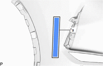
25. INSTALL NO. 1 MOULDING TAPE
HINT:
- Use the same procedure for the LH side and RH side.
- When installing the No. 1 moulding tape, heat the front bumper assembly using a heat light.
Heating Temperature:
| Item | Temperature |
|---|---|
| Front Bumper Assembly | 20 to 30°C (68 to 86°F) |
CAUTION:
- Do not touch the heat light and heated parts, touching the heat light may result in burns.
- Touching heated parts for a long time may result in burns.
.png)
| *a | Heated Part |
| *b | Heat Light |
NOTICE:
Do not heat the front bumper assembly excessively.
(a) Clean the front bumper assembly surface.
(1) Using a heat light, heat the front bumper assembly surface.
(2) Remove the double-sided tape from the front bumper assembly.
(3) Wipe off any tape adhesive residue with cleaner.
(b) Remove the release paper from a new No. 1 moulding tape.
HINT:
After removing the release paper, keep the exposed adhesive free from foreign matter.
| (c) Install the No. 1 moulding tape as shown in the illustration. HINT: Press the No. 1 moulding tape firmly to install it. |
|
26. INSTALL NO. 2 WASHER BRACKET (w/ Headlight Cleaner System)
HINT:
When installing the No. 2 washer bracket, heat the front bumper assembly using a heat light.
Heating Temperature:
| Item | Temperature |
|---|---|
| Front Bumper Assembly | 20 to 30°C (68 to 86°F) |
CAUTION:
- Do not touch the heat light and heated parts, touching the heat light may result in burns.
- Touching heated parts for a long time may result in burns.
| *a | Heated Part |
| *b | Heat Light |
NOTICE:
Do not heat the front bumper assembly excessively.
(a) Clean the front bumper assembly surface.
(1) Using a heat light, heat the front bumper assembly surface.
(2) Remove the double-sided tape from the front bumper assembly.
(3) Wipe off any tape adhesive residue with cleaner.
(b) Remove the release paper from a new No. 2 washer bracket.
HINT:
After removing the release paper, keep the exposed adhesive free from foreign matter.
| (c) Install the No. 2 washer bracket. HINT: Press the No. 2 washer bracket firmly to install it. |
|
.png)
27. INSTALL NO. 1 WASHER BRACKET (w/ Headlight Cleaner System)
HINT:
Use the same procedure for the No. 2 washer bracket.
28. INSTALL HEADLIGHT CLEANER HOSE (w/ Headlight Cleaner System)
(a) Engage the 8 clamps to install the headlight cleaner hose.
.png)
29. INSTALL HEADLIGHT WASHER ACTUATOR SUB-ASSEMBLY LH (w/ Headlight Cleaner System)
Click here .gif)
30. INSTALL HEADLIGHT WASHER ACTUATOR SUB-ASSEMBLY RH (w/ Headlight Cleaner System)
HINT:
Use the same procedure as for the LH side.
31. INSTALL HEADLIGHT WASHER COVER LH (w/ Headlight Cleaner System)
Click here
32. INSTALL HEADLIGHT WASHER COVER RH (w/ Headlight Cleaner System)
HINT:
Use the same procedure as for the LH side.
33. INSTALL ULTRASONIC SENSOR CLIP (w/ Intuitive Parking Assist System)
HINT:
- Use the same procedure for all ultrasonic sensor clips.
- When removing the ultrasonic sensor clip, heat the front bumper assembly using a heat light.
Heating Temperature:
| Item | Temperature |
|---|---|
| Front Bumper Assembly | 20 to 30°C (68 to 86°F) |
CAUTION:
- Do not touch the heat light and heated parts, touching the heat light may result in burns.
- Touching heated parts for a long time may result in burns.
| *a | Heated Part |
| *b | Heat Light |
NOTICE:
Do not heat the front bumper assembly excessively.
(a) Clean the front bumper assembly surface.
(1) Using a heat light, heat the front bumper assembly surface.
(2) Remove the double-sided tape from the front bumper assembly.
(3) Wipe off any tape adhesive residue with cleaner.
(b) Using a brush or felt, apply primer or equivalent to the ultrasonic sensor clip installation area.
 | Primer |
(c) Remove the release paper from a new ultrasonic sensor clip.
HINT:
After removing the release paper, keep the exposed adhesive free from foreign matter.
| (d) Install the ultrasonic sensor clip as shown in the illustration. HINT: Press the ultrasonic sensor clip firmly to install it. |
|
34. INSTALL NO. 4 ENGINE ROOM WIRE (w/ Intuitive Parking Assist System)
(a) Engage the 12 clamps to install the No. 4 engine room wire.
.png)
35. INSTALL FRONT CORNER ULTRASONIC SENSOR RETAINER (w/ Intuitive Parking Assist System)
Click here
36. INSTALL FRONT CORNER ULTRASONIC SENSOR (w/ Intuitive Parking Assist System)
Click here
37. INSTALL FRONT CENTER ULTRASONIC SENSOR (w/ Intuitive Parking Assist System)
Click here
38. INSTALL FRONT TELEVISION CAMERA ASSEMBLY (w/ Panoramic View Monitor System)
Click here
39. INSTALL TELEVISION CAMERA WIRE (w/ Panoramic View Monitor System)
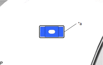
| (a) Connect the connector to install the television camera wire. |
|
.png)
40. INSTALL MILLIMETER WAVE RADAR SENSOR ASSEMBLY
Click here
41. INSTALL CONNECTOR COVER (w/o Fog Light)
HINT:
Use the same procedure for all connector covers.
| (a) Engage the clamp to install the connector cover. |
|
.png)
42. INSTALL FRONT BUMPER HOLE COVER ASSEMBLY LH (w/o Fog Light)
(a) Install the front bumper hole cover assembly LH with the clip and 2 screws.
.png)
| | Clip |
| | Screw |
(b) w/ Headlight Cleaner System:
| (1) Engage the clamp. |
|
.png)
43. INSTALL FRONT BUMPER HOLE COVER ASSEMBLY RH (w/o Fog Light)
HINT:
Use the same procedure as for the LH side.
44. INSTALL FOG LIGHT ASSEMBLY LH (w/ Fog Light)
Click here
45. INSTALL FOG LIGHT ASSEMBLY RH (w/ Fog Light)
HINT:
Use the same procedure as for the LH side.
46. INSTALL FRONT BUMPER ARM HOLE COVER LH (for Type A)
| (a) Engage the 3 guides. |
|
.png)
(b) Install the front bumper arm hole cover LH with the screw and clip.
.png)
| | Screw |
| | Clip |
47. INSTALL FRONT BUMPER ARM HOLE COVER LH (for Type B)
| (a) Engage the 3 guides. |
|
.png)
(b) Install the front bumper arm hole cover LH with the screw and clip.
.png)
| | Screw |
| | Clip |
 Disassembly
DISASSEMBLY PROCEDURE 1. REMOVE FRONT BUMPER ARM HOLE COVER LH (for Type A) (a) Remove the screw and clip. Screw Clip (b) Disengage the 3 guides to remove the front bumper arm hole ...

Other materials:
Lexus RX (RX 350L, RX450h) 2016-2026 Repair Manual > Rear Brake: Disassembly
DISASSEMBLY CAUTION / NOTICE / HINT NOTICE:
If the rear disc brake cylinder assembly has been disassembled, perform air bleeding for the rear disc brake cylinder assembly.
Click here
Make sure not to scratch, damage or apply excessive force to any of the internal components of the rear disc b ...
Lexus RX (RX 350L, RX450h) 2016-2026 Repair Manual > Audio And Visual System (for 8 Inch Display): Air Conditioner ECU Vehicle Information Reading/Writing Processor Malfunction (B15F5)
DESCRIPTION This DTC is stored when items controlled by the air conditioning amplifier assembly cannot be customized via the audio and visual system vehicle customization screen. HINT: The air conditioning amplifier assembly controls the air conditioning system related items that are customizable vi ...
Lexus RX (RX 350L, RX450h) 2016-{YEAR} Owners Manual
- For your information
- Pictorial index
- For safety and security
- Instrument cluster
- Operation of each component
- Driving
- Lexus Display Audio system
- Interior features
- Maintenance and care
- When trouble arises
- Vehicle specifications
- For owners
Lexus RX (RX 350L, RX450h) 2016-{YEAR} Repair Manual

0.0116