Lexus RX (RX 350L, RX450h) 2016-2026 Repair Manual: Horn
Components
COMPONENTS
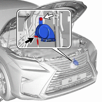
ILLUSTRATION
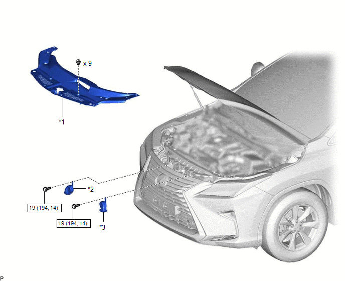
| *1 | COOL AIR INTAKE DUCT SEAL | *2 | HIGH PITCHED HORN ASSEMBLY |
| *3 | LOW PITCHED HORN ASSEMBLY | - | - |
.png) | N*m (kgf*cm, ft.*lbf): Specified torque | - | - |
Inspection
INSPECTION
PROCEDURE
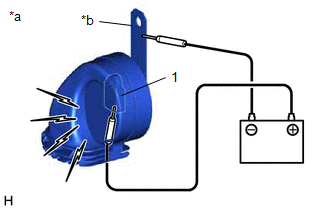
1. INSPECT HIGH PITCHED HORN ASSEMBLY
| (a) Apply battery voltage and check the operation of the high pitched horn assembly according to the table below. OK:
If the result is not as specified, replace the high pitched horn assembly. |
|
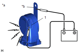
2. INSPECT LOW PITCHED HORN ASSEMBLY
| (a) Apply battery voltage and check the operation of the low pitched horn assembly according to the table below. OK:
If the result is not as specified, replace the low pitched horn assembly. |
|
Removal
REMOVAL
PROCEDURE
1. REMOVE COOL AIR INTAKE DUCT SEAL
Click here .gif)
2. REMOVE HIGH PITCHED HORN ASSEMBLY
| (a) Disconnect the connector. |
|
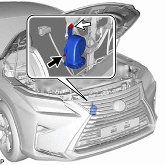
(b) Remove the bolt and high pitched horn assembly.
3. REMOVE LOW PITCHED HORN ASSEMBLY
| (a) Disconnect the connector. |
|
(b) Remove the bolt and low pitched horn assembly.
Installation
INSTALLATION
PROCEDURE
1. INSTALL LOW PITCHED HORN ASSEMBLY
(a) Install the low pitched horn assembly with the bolt.
Torque:
19 N·m {194 kgf·cm, 14 ft·lbf}
(b) Connect the connector.
2. INSTALL HIGH PITCHED HORN ASSEMBLY
(a) Install the high pitched horn assembly with the bolt.
Torque:
19 N·m {194 kgf·cm, 14 ft·lbf}
(b) Connect the connector.
3. INSTALL COOL AIR INTAKE DUCT SEAL
Click here .gif)
 Horn
Horn
...
 Horn System
...
Other materials:
Lexus RX (RX 350L, RX450h) 2016-2026 Repair Manual > Brake Booster: On-vehicle Inspection
ON-VEHICLE INSPECTION PROCEDURE 1. INSPECT BRAKE BOOSTER ASSEMBLY (a) Airtightness check (1) Start the engine and stop it after 1 or 2 minutes. Slowly depress the brake pedal several times. If the brake pedal can be depressed nearly to the floor the first time, but on the 2nd and 3rd time cannot ...
Lexus RX (RX 350L, RX450h) 2016-2026 Repair Manual > Automatic Transaxle System: Dtc Check / Clear
DTC CHECK / CLEAR NOTICE: When the diagnosis system is changed from normal mode to check mode or vice versa, all DTCs and freeze frame data recorded in normal mode are cleared. Before changing modes, always check and make a note of DTCs and freeze frame data. HINT:
DTCs which are stored in the EC ...
Lexus RX (RX 350L, RX450h) 2016-{YEAR} Owners Manual
- For your information
- Pictorial index
- For safety and security
- Instrument cluster
- Operation of each component
- Driving
- Lexus Display Audio system
- Interior features
- Maintenance and care
- When trouble arises
- Vehicle specifications
- For owners
Lexus RX (RX 350L, RX450h) 2016-{YEAR} Repair Manual

0.0101