Lexus RX (RX 350L, RX450h) 2016-2026 Repair Manual: Automatic High Beam System (B124B)
DESCRIPTION
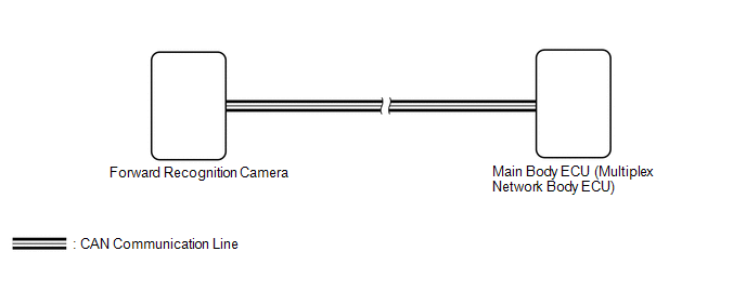
The main body ECU (multiplex network body ECU) determines the status of the automatic high beam system based on the automatic high beam system signal from the forward recognition camera.
| DTC No. | Detection Item | DTC Detection Condition | Trouble Area | DTC Output from |
|---|---|---|---|---|
| B124B | Automatic High Beam System | Malfunction in automatic high beam system |
| Main Body |
- *: w/ Road Sign Assist System
WIRING DIAGRAM
CAUTION / NOTICE / HINT
NOTICE:
-
The lighting system uses the CAN communication system. Inspect the communication functions by following How to Proceed with Troubleshooting. Troubleshoot the automatic high beam system after confirming that the communication systems are functioning properly.
Click here
.gif)
-
Before replacing the main body ECU (multiplex network body ECU), refer to Registration.
Click here
HINT:
If the forward recognition camera stores a DTC for a malfunction of any of the following, this DTC will be stored simultaneously.- Speed sensor
- Yaw rate sensor
- Millimeter wave radar sensor
- CAN communication system
PROCEDURE
| 1. | CHECK FOR DTC (HEALTH CHECK) |
(a) Connect the Techstream to the DLC3.
(b) Turn the engine switch on (IG).
(c) Turn the Techstream on.
(d) Enter the following menus: System Select / Health Check.
(e) Check for DTCs.
| Result | Proceed to |
|---|---|
| Only DTC B124B is output | A |
| DTC B124B and other DTCs are output | B |
| B | .gif) | GO TO OTHER DTC CHART |
|
.gif)
| 2. | CHECK FRONT CAMERA SYSTEM |
(a) Check if a dynamic radar cruise control system, lane control system, road sign assist system* or pre-collision system warning message is displayed on the multi-information display.
Click here
OK:
No dynamic radar cruise control system, lane control system, road sign assist system* or pre-collision system warning messages are displayed.
- *: w/ Road Sign Assist System
| OK | | REPLACE MAIN BODY ECU (MULTIPLEX NETWORK BODY ECU) |
| NG | | GO TO FRONT CAMERA SYSTEM |
 Vehicle Control History
VEHICLE CONTROL HISTORY CHECK VEHICLE CONTROL HISTORY HINT:
The vehicle control history data stores the history of the reject function and system protection operations.
The number of occurrences, ...
 Light Sensor Circuit (B1244)
DESCRIPTION The automatic light control sensor detects ambient light. The sensor creates an electrical signal based on the amount of light detected, and sends the signal to the main body ECU (multiple ...
Other materials:
Lexus RX (RX 350L, RX450h) 2016-2026 Repair Manual > Wireless Door Lock Control System: Operation Check
OPERATION CHECK NOTICE WHEN CHECKING FOLLOWING (a) Wireless door lock/unlock function: This wireless door lock control function operates only when the following 3 conditions are met: (1) The engine switch is off. (2) All of the doors are closed. (3) The power door lock control system is operating pr ...
Lexus RX (RX 350L, RX450h) 2016-2026 Repair Manual > Transmission Control Cable: Adjustment
ADJUSTMENT CAUTION / NOTICE / HINT NOTICE: Before installing the transmission control cable assembly, check that the park/neutral position switch assembly and the shift lever are in neutral. PROCEDURE 1. SECURE VEHICLE (a) Fully apply the parking brake and chock a wheel. CAUTION:
Make sure to app ...
Lexus RX (RX 350L, RX450h) 2016-{YEAR} Owners Manual
- For your information
- Pictorial index
- For safety and security
- Instrument cluster
- Operation of each component
- Driving
- Lexus Display Audio system
- Interior features
- Maintenance and care
- When trouble arises
- Vehicle specifications
- For owners
Lexus RX (RX 350L, RX450h) 2016-{YEAR} Repair Manual

0.0099