Lexus RX (RX 350L, RX450h) 2016-2026 Repair Manual: Headlight Beam Level Control Motor LH Lost Communication (B2424,B2425)
DESCRIPTION
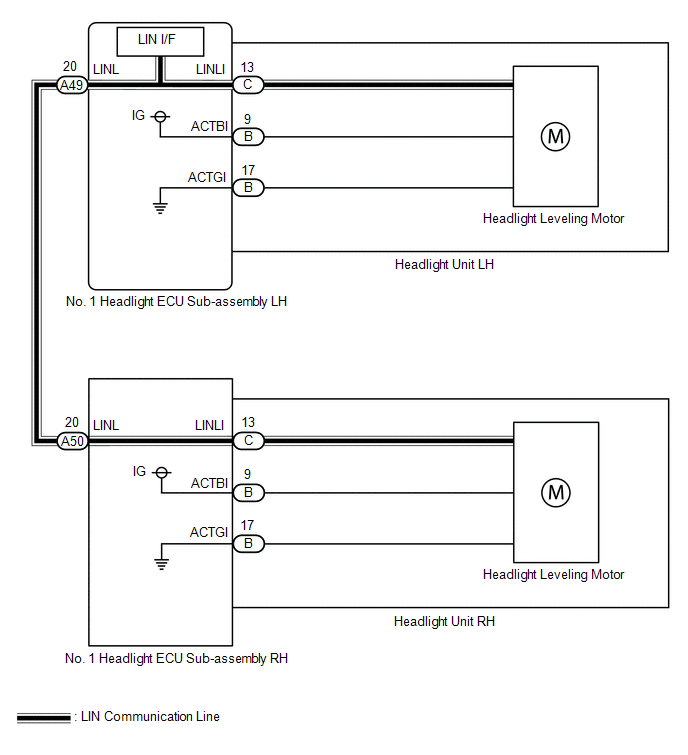
Each No. 1 headlight ECU sub-assembly and headlight leveling motor communicate via LIN communication.
The headlight leveling motor operates according to power supplied and automatic headlight beam level control signals from its respective No. 1 headlight ECU sub-assembly and sends its operating state to the No. 1 headlight ECU sub-assembly.
| DTC No. | Detection Item | DTC Detection Condition | Trouble Area | DTC Output from |
|---|---|---|---|---|
| B2424 | Headlight Beam Level Control Motor LH Lost Communication |
|
| AFS |
| B2425 | Headlight Beam Level Control Motor RH Lost Communication |
|
| AFS |
WIRING DIAGRAM
CAUTION / NOTICE / HINT
NOTICE:
-
If the No. 1 headlight ECU sub-assembly LH has been replaced, it is necessary to synchronize the vehicle information and initialize the No. 1 headlight ECU sub-assembly LH.
Click here
.gif)
-
If the headlight assembly LH has been replaced, it is necessary to synchronize the vehicle information and initialize the No. 1 headlight ECU sub-assembly LH.*
Click here
- When replacing the No. 1 headlight ECU sub-assembly LH, always replace it with a new one. If a No. 1 headlight ECU sub-assembly LH which was installed to another vehicle is used, the information stored in it will not match the information from the vehicle and a DTC may be stored.
-
When replacing the headlight assembly LH, always replace it with a new one. If a headlight assembly LH which was installed to another vehicle is used, the information stored in it will not match the information from the vehicle and a DTC may be stored.*
- *: for TMMC Made
PROCEDURE
| 1. | CLEAR DTC |
(a) Connect the Techstream to the DLC3.
(b) Turn the engine switch on (IG).
(c) Turn the Techstream on.
(d) Enter the following menus: Body Electrical / AFS / Trouble Codes.
(e) Clear the DTCs.
Body Electrical > AFS > Clear DTCs
|
.gif)
| 2. | CHECK FOR DTC |
(a) Connect the Techstream to the DLC3.
(b) Turn the engine switch on (IG).
(c) Wait 10 seconds or more.
(d) Turn the Techstream on.
(e) Enter the following menus: Body Electrical / AFS / Trouble Codes.
(f) Check for DTCs.
Body Electrical > AFS > Trouble CodesOK:
DTC B2424 and B2425 are not output.
| Result | Proceed to |
|---|---|
| OK | A |
| NG (DTC B2424 is output) | B |
| NG (DTC B2425 is output) | C |
| NG (DTC B2424 and B2425 are output) | D |
| A | .gif) | USE SIMULATION METHOD TO CHECK |
| C | | GO TO STEP 4 |
| D | | GO TO STEP 7 |
|
| 3. | INSPECT NO. 1 HEADLIGHT ECU SUB-ASSEMBLY LH |

| *a | Component without harness connected (No. 1 Headlight ECU Sub-assembly LH) | - | - |
(a) Remove the No. 1 headlight ECU sub-assembly LH.
Click here
(b) Measure the resistance according to the value(s) in the table below.
Standard Resistance:
| Tester Connection | Condition | Specified Condition |
|---|---|---|
| A49-20 (LINL) - C-13 (LINLI) | Always | Below 1 Ω |
| Result | Proceed to |
|---|---|
| OK (for TMC Made) | A |
| OK (for TMMC Made) | B |
| NG | C |
| A | | REPLACE HEADLIGHT UNIT LH |
| B | | REPLACE HEADLIGHT ASSEMBLY LH |
| C | | REPLACE NO. 1 HEADLIGHT ECU SUB-ASSEMBLY LH |
| 4. | CHECK HARNESS AND CONNECTOR (NO. 1 HEADLIGHT ECU SUB-ASSEMBLY LH - NO. 1 HEADLIGHT ECU SUB-ASSEMBLY RH) |
(a) Disconnect the A49 No. 1 headlight ECU sub-assembly LH connector.
(b) Disconnect the A50 No. 1 headlight ECU sub-assembly RH connector.
(c) Measure the resistance according to the value(s) in the table below.
Standard Resistance:
| Tester Connection | Condition | Specified Condition |
|---|---|---|
| A49-20 (LINL) - A50-20 (LINL) | Always | Below 1 Ω |
| NG | | REPAIR OR REPLACE HARNESS OR CONNECTOR |
|
| 5. | CHECK NO. 1 HEADLIGHT ECU SUB-ASSEMBLY LH (LINL TERMINAL SIGNAL OUTPUT) |
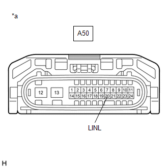
| *a | Front view of wire harness connector (to No. 1 Headlight ECU Sub-assembly RH) |
(a) Connect the A49 No. 1 headlight ECU sub-assembly LH connector.
(b) Using a Techstream, check the waveform.
OK:
| Tester Connection | Condition | Specified Condition |
|---|---|---|
| A50-20 (LINL) - Body ground | Engine switch on (IG) | Pulse generation |
| NG | | REPLACE NO. 1 HEADLIGHT ECU SUB-ASSEMBLY LH |
|
| 6. | INSPECT NO. 1 HEADLIGHT ECU SUB-ASSEMBLY RH |
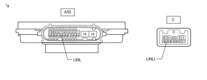
| *a | Component without harness connected (No. 1 Headlight ECU Sub-assembly RH) | - | - |
(a) Remove the No. 1 headlight ECU sub-assembly RH.
Click here
(b) Measure the resistance according to the value(s) in the table below.
Standard Resistance:
| Tester Connection | Condition | Specified Condition |
|---|---|---|
| A50-20 (LINL) - C-13 (LINLI) | Always | Below 1 Ω |
| Result | Proceed to |
|---|---|
| OK (for TMC Made) | A |
| OK (for TMMC Made) | B |
| NG | C |
| A | | REPLACE HEADLIGHT UNIT RH |
| B | | REPLACE HEADLIGHT ASSEMBLY RH |
| C | | REPLACE NO. 1 HEADLIGHT ECU SUB-ASSEMBLY RH |
| 7. | CHECK HARNESS AND CONNECTOR (NO. 1 HEADLIGHT ECU SUB-ASSEMBLY LH - NO. 1 HEADLIGHT ECU SUB-ASSEMBLY RH) |
(a) Disconnect the A49 No. 1 headlight ECU sub-assembly LH connector.
(b) Disconnect the A50 No. 1 headlight ECU sub-assembly RH connector.
(c) Measure the resistance according to the value(s) in the table below.
Standard Resistance:
| Tester Connection | Condition | Specified Condition |
|---|---|---|
| A49-20 (LINL) or A50-20 (LINL) - Body ground | Always | 10 kΩ or higher |
| NG | | REPAIR OR REPLACE HARNESS OR CONNECTOR |
|
| 8. | CLEAR DTC |
(a) Connect the A49 No. 1 headlight ECU sub-assembly LH connector.
(b) Connect the Techstream to the DLC3.
(c) Turn the engine switch on (IG).
(d) Turn the Techstream on.
(e) Enter the following menus: Body Electrical / AFS / Trouble Codes.
(f) Clear the DTCs.
Body Electrical > AFS > Clear DTCs
|
| 9. | CHECK FOR DTC |
(a) Connect the Techstream to the DLC3.
(b) Turn the engine switch on (IG).
(c) Wait 10 seconds or more.
(d) Turn the Techstream on.
(e) Enter the following menus: Body Electrical / AFS / Trouble Codes.
(f) Check for DTCs.
Body Electrical > AFS > Trouble Codes| Result | Proceed to |
|---|---|
| DTC B2425 is output | A |
| DTC B2424 and B2425 are output | B |
| B | | GO TO STEP 13 |
|
| 10. | CHECK NO. 1 HEADLIGHT ECU SUB-ASSEMBLY RH |
(a) Remove the No. 1 headlight ECU sub-assembly RH.
Click here
(b) Connect the A50 No. 1 headlight ECU sub-assembly RH connector.
|
| 11. | CLEAR DTC |
(a) Connect the Techstream to the DLC3.
(b) Turn the engine switch on (IG).
(c) Turn the Techstream on.
(d) Enter the following menus: Body Electrical / AFS / Trouble Codes.
(e) Clear the DTCs.
Body Electrical > AFS > Clear DTCs
|
| 12. | CHECK FOR DTC |
(a) Connect the Techstream to the DLC3.
(b) Turn the engine switch on (IG).
(c) Wait 10 seconds or more.
(d) Turn the Techstream on.
(e) Enter the following menus: Body Electrical / AFS / Trouble Codes.
(f) Check for DTCs.
Body Electrical > AFS > Trouble Codes| Result | Proceed to |
|---|---|
| DTC B2425 is output (for TMC Made) | A |
| DTC B2425 is output (for TMMC Made) | B |
| DTC B2424 and B2425 are output | C |
| A | | REPLACE HEADLIGHT UNIT RH |
| B | | REPLACE HEADLIGHT ASSEMBLY RH |
| C | | REPLACE NO. 1 HEADLIGHT ECU SUB-ASSEMBLY RH |
| 13. | CHECK NO. 1 HEADLIGHT ECU SUB-ASSEMBLY LH |
(a) Remove the No. 1 headlight ECU sub-assembly LH.
Click here
(b) Connect the A49 No. 1 headlight ECU sub-assembly LH connector.
(c) Connect the A50 No. 1 headlight ECU sub-assembly RH connector.
|
| 14. | CLEAR DTC |
(a) Connect the Techstream to the DLC3.
(b) Turn the engine switch on (IG).
(c) Turn the Techstream on.
(d) Enter the following menus: Body Electrical / AFS / Trouble Codes.
(e) Clear the DTCs.
Body Electrical > AFS > Clear DTCs
|
| 15. | CHECK FOR DTC |
(a) Connect the Techstream to the DLC3.
(b) Turn the engine switch on (IG).
(c) Wait 10 seconds or more.
(d) Turn the Techstream on.
(e) Enter the following menus: Body Electrical / AFS / Trouble Codes.
(f) Check for DTCs.
Body Electrical > AFS > Trouble Codes| Result | Proceed to |
|---|---|
| DTC B2424 is output (for TMC Made) | A |
| DTC B2424 is output (for TMMC Made) | B |
| DTC B2424 and B2425 are output | C |
| A | | REPLACE HEADLIGHT UNIT LH |
| B | | REPLACE HEADLIGHT ASSEMBLY LH |
| C | | REPLACE NO. 1 HEADLIGHT ECU SUB-ASSEMBLY LH |
 Height Control Sensor (B2416,B241A)
DESCRIPTION The No. 1 headlight ECU sub-assembly LH determines the vehicle height and performs automatic headlight beam level control based on signals from the rear height control sensor sub-assembly ...
 Right Headlight ECU Malfunction (B242C,B242D)
DESCRIPTION The No. 1 headlight ECU sub-assembly LH stores a DTC if it detects an internal malfunction. for Multiple Beam Headlight DTC No. Detection Item DTC Detection Condition Trouble Area ...
Other materials:
Lexus RX (RX 350L, RX450h) 2016-2026 Repair Manual > Audio And Visual System (for 12.3 Inch Display): GPS Antenna Connection Malfunction(short) (B15C0,B15C1)
DESCRIPTION These DTCs are stored when a malfunction occurs in the navigation antenna assembly. DTC No. Detection Item DTC Detection Condition Trouble Area B15C0 GPS Antenna Connection Malfunction(short) Navigation antenna assembly error
Navigation antenna assembly
Antenna co ...
Lexus RX (RX 350L, RX450h) 2016-2026 Repair Manual > Lighting System (w/o Automatic Headlight Beam Level Control System): Headlight Dimmer Switch Circuit
DESCRIPTION The main body ECU (multiplex network body ECU) receives the following switch information:
Light control switch in DRL OFF*, tail, head, AUTO position
Dimmer switch in high, low or high flash (pass) position
*: w/ DRL OFF Switch
WIRING DIAGRAM CAUTION / NOTICE / HINT NOTICE ...
Lexus RX (RX 350L, RX450h) 2016-{YEAR} Owners Manual
- For your information
- Pictorial index
- For safety and security
- Instrument cluster
- Operation of each component
- Driving
- Lexus Display Audio system
- Interior features
- Maintenance and care
- When trouble arises
- Vehicle specifications
- For owners
Lexus RX (RX 350L, RX450h) 2016-{YEAR} Repair Manual

0.0109