Lexus RX (RX 350L, RX450h) 2016-2026 Repair Manual: Abnormal Height Sensor Data at Initialization (B2452)
DESCRIPTION
The No. 1 headlight ECU sub-assembly LH stores this DTC if the value from the rear height control sensor sub-assembly RH is out of range when performing initialization of the No. 1 headlight ECU sub-assembly LH, such as when the vehicle is not level or jacked up.
for Multiple Beam Headlight| DTC No. | Detection Item | DTC Detection Condition | Trouble Area | DTC Output from |
|---|---|---|---|---|
| B2452 | Abnormal Height Sensor Data at Initialization |
|
| AFS |
| DTC No. | Detection Item | DTC Detection Condition | Trouble Area | DTC Output from |
|---|---|---|---|---|
| B2452 | Abnormal Height Sensor Data at Initialization |
|
| HL AutoLeveling |
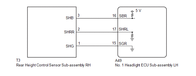
WIRING DIAGRAM
CAUTION / NOTICE / HINT
NOTICE:
-
If the No. 1 headlight ECU sub-assembly LH has been replaced, it is necessary to synchronize the vehicle information and initialize the No. 1 headlight ECU sub-assembly LH.
Click here
.gif)
-
If the headlight assembly LH has been replaced, it is necessary to synchronize the vehicle information and initialize the No. 1 headlight ECU sub-assembly LH.*
Click here
-
If any of the following are performed, it is necessary to initialize the No. 1 headlight ECU sub-assembly LH.
Click here
- Replacement of the rear height control sensor sub-assembly RH
- Removal/installation of the rear height control sensor sub-assembly RH
- Work that changes the vehicle height such as replacement of suspension components
- When replacing the No. 1 headlight ECU sub-assembly LH, always replace it with a new one. If a No. 1 headlight ECU sub-assembly LH which was installed to another vehicle is used, the information stored in it will not match the information from the vehicle and a DTC may be stored.
-
When replacing the headlight assembly LH, always replace it with a new one. If a headlight assembly LH which was installed to another vehicle is used, the information stored in it will not match the information from the vehicle and a DTC may be stored.*
- *: for TMMC Made
PROCEDURE
| 1. | INITIALIZATION NO. 1 HEADLIGHT ECU SUB-ASSEMBLY LH |
(a) Perform initialization of the No. 1 headlight ECU sub-assembly LH.
Click here
|
.gif)
| 2. | CONFIRM MODEL |
(a) Choose the model to be inspected.
| Result | Proceed to |
|---|---|
| for Multiple Beam Headlight | A |
| for Single Beam Headlight | B |
| B | .gif) | GO TO STEP 5 |
|
| 3. | CLEAR DTC |
(a) Connect the Techstream to the DLC3.
(b) Turn the engine switch on (IG).
(c) Turn the Techstream on.
(d) Enter the following menus: Body Electrical / AFS / Trouble Codes.
(e) Clear the DTCs.
Body Electrical > AFS > Clear DTCs
|
| 4. | CHECK FOR DTC |
(a) Connect the Techstream to the DLC3.
(b) Turn the engine switch on (IG).
(c) Turn the Techstream on.
(d) Enter the following menus: Body Electrical / AFS / Trouble Codes.
(e) Check for DTCs.
Body Electrical > AFS > Trouble CodesOK:
DTC B2452 is not output.
| OK | | END (INITIALIZATION WAS NOT COMPLETED) |
| NG | | GO TO STEP 7 |
| 5. | CLEAR DTC |
(a) Connect the Techstream to the DLC3.
(b) Turn the engine switch on (IG).
(c) Turn the Techstream on.
(d) Enter the following menus: Body Electrical / HL AutoLeveling / Trouble Codes.
(e) Clear the DTCs.
Body Electrical > HL AutoLeveling > Clear DTCs
|
| 6. | CHECK FOR DTC |
(a) Connect the Techstream to the DLC3.
(b) Turn the engine switch on (IG).
(c) Turn the Techstream on.
(d) Enter the following menus: Body Electrical / HL AutoLeveling / Trouble Codes.
(e) Check for DTCs.
Body Electrical > HL AutoLeveling > Trouble CodesOK:
DTC B2452 is not output.
| OK | | END (INITIALIZATION WAS NOT COMPLETED) |
|
| 7. | CHECK REAR HEIGHT CONTROL SENSOR SUB-ASSEMBLY RH |
(a) Check the installation condition of the rear height control sensor sub-assembly RH.
OK:
Rear height control sensor sub-assembly RH is installed correctly.
| NG | | INSTALL PARTS CORRECTLY |
|
| 8. | INSPECT REAR HEIGHT CONTROL SENSOR SUB-ASSEMBLY RH |
(a) Remove the rear height control sensor sub-assembly RH.
Click here
(b) Inspect the rear height control sensor sub-assembly RH.
Click here
| NG | | REPLACE REAR HEIGHT CONTROL SENSOR SUB-ASSEMBLY RH |
|
| 9. | CHECK HARNESS AND CONNECTOR (REAR HEIGHT CONTROL SENSOR SUB-ASSEMBLY RH - NO. 1 HEADLIGHT ECU SUB-ASSEMBLY LH) |
(a) Disconnect the A49 No. 1 headlight ECU sub-assembly LH connector.
(b) Measure the resistance according to the value(s) in the table below.
Standard Resistance:
| Tester Connection | Condition | Specified Condition |
|---|---|---|
| T3-3 (SHB) - A49-16 (SBR) | Always | Below 1 Ω |
| T3-2 (SHRR) - A49-17 (SHRL) | Always | Below 1 Ω |
| T3-1 (SHG) - A49-15 (SGR) | Always | Below 1 Ω |
| T3-3 (SHB) or A49-16 (SBR) - Body ground | Always | 10 kΩ or higher |
| T3-2 (SHRR) or A49-17 (SHRL) - Body ground | Always | 10 kΩ or higher |
| OK | | REPLACE NO. 1 HEADLIGHT ECU SUB-ASSEMBLY LH |
| NG | | REPAIR OR REPLACE HARNESS OR CONNECTOR |
 Variation Code not Written (B2451)
DESCRIPTION The No. 1 headlight ECU sub-assembly LH stores this DTC if the vehicle specifications have not been stored. DTC No. Detection Item DTC Detection Condition Trouble Area DTC Outpu ...
 Left Headlight ECU Variation Error (B2456)
DESCRIPTION This DTC is stored if the No. 1 headlight ECU sub-assembly LH for another destination is installed. DTC No. Detection Item DTC Detection Condition Trouble Area DTC Output from ...
Other materials:
Lexus RX (RX 350L, RX450h) 2016-2026 Repair Manual > Airbag System: SRS Warning Light Remains ON
DESCRIPTION The SRS warning light is located in the combination meter assembly. When the SRS is normal, the SRS warning light comes on for approximately 6 seconds after the engine switch is turned from off to on (IG), and then turns off automatically. If there is a malfunction in the SRS, the SRS wa ...
Lexus RX (RX 350L, RX450h) 2016-2026 Repair Manual > Airbag System: Parts Location
PARTS LOCATION ILLUSTRATION *A w/o Rear No. 2 Seat - - *1 FRONT AIRBAG SENSOR LH *2 FRONT AIRBAG SENSOR RH *3 DOOR SIDE AIRBAG SENSOR LH *4 DOOR SIDE AIRBAG SENSOR RH *5 REAR AIRBAG SENSOR LH *6 REAR AIRBAG SENSOR RH *7 CURTAIN SHIELD AIRBAG ASSEMBLY LH ...
Lexus RX (RX 350L, RX450h) 2016-{YEAR} Owners Manual
- For your information
- Pictorial index
- For safety and security
- Instrument cluster
- Operation of each component
- Driving
- Lexus Display Audio system
- Interior features
- Maintenance and care
- When trouble arises
- Vehicle specifications
- For owners
Lexus RX (RX 350L, RX450h) 2016-{YEAR} Repair Manual

0.0108