Lexus RX (RX 350L, RX450h) 2016-2026 Repair Manual: Removal
REMOVAL
CAUTION / NOTICE / HINT
The necessary procedures (adjustment, calibration, initialization or registration) that must be performed after parts are removed and installed, or replaced during sliding roof glass sub-assembly, sliding roof housing sub-assembly, sliding roof drive gear sub-assembly or sliding roof drive cable sub-assembly removal/installation are shown below.
Necessary Procedures After Parts Removed/Installed/Replaced| Replaced Part or Performed Procedure | Necessary Procedure | Effect/Inoperative Function when Necessary Procedure not Performed | Link |
|---|---|---|---|
| Disconnect cable from negative battery terminal | Memorize steering angle neutral point | Lane Control System | |
| Pre-collision System | |||
| Intelligent Clearance Sonar System*1 | |||
| Lighting System (w/ Automatic Headlight Beam Level Control System) | | ||
| Parking Assist Monitor System | | ||
| Panoramic View Monitor System | | ||
| Initialize back door lock | Power Door Lock Control System | | |
| Reset back door close position | Power Back Door System (w/ Outside Door Control Switch) | | |
| Initialize Sliding Roof System |
| |
*1: When performing learning using the Techstream.
Click here .gif)
CAUTION:
Some of these service operations affect the SRS airbag system. Read the precautionary notices concerning the SRS airbag system before servicing.
.png)
Click here
PROCEDURE
1. REMOVE SLIDING ROOF DRIVE GEAR SUB-ASSEMBLY
HINT:
Perform this procedure only when replacement of the sliding roof drive gear sub-assembly is necessary.
(a) Remove the map light assembly.
Click here
(b) Remove the bolt.
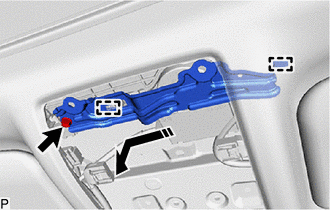
.png) | Remove in this Direction |
(c) Disengage the 2 guides as shown in the illustration to remove the map light bracket.
| (d) Disconnect the connector. |
|
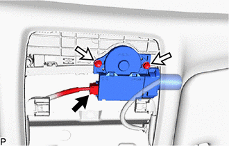
(e) Remove the 2 bolts and sliding roof drive gear sub-assembly.
NOTICE:
Be careful not to drop the sliding roof drive gear sub-assembly.
2. REMOVE SLIDING ROOF SIDE GARNISH LH
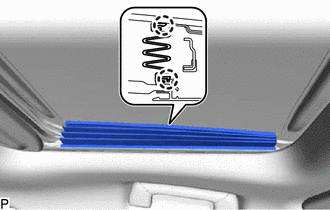
| (a) Disengage the 2 claws to remove the sliding roof side garnish LH. |
|
3. REMOVE SLIDING ROOF SIDE GARNISH RH
HINT:
Use the same procedure as for the LH side.
4. REMOVE SLIDING ROOF GLASS SUB-ASSEMBLY
(a) Move the sliding roof glass sub-assembly to the fully closed position.
(b) Using a T25 "TORX" socket wrench, remove the 4 screws and sliding roof glass sub-assembly.
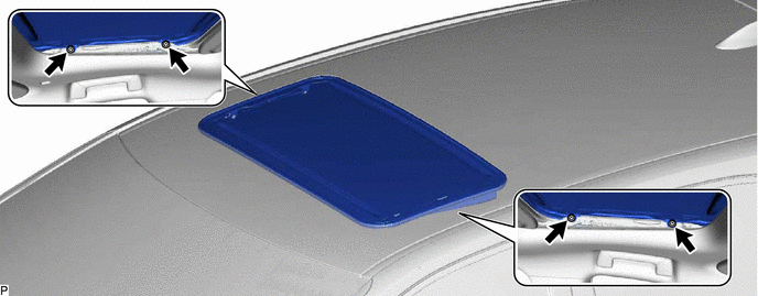
NOTICE:
To prevent the sliding roof glass sub-assembly and sliding roof drive gear sub-assembly from becoming misaligned, move the sliding roof glass sub-assembly (sliding roof drive cable sub-assembly) to the fully closed position before removing.
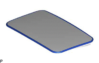
5. REMOVE SLIDING ROOF WEATHERSTRIP (for TMMC Made)
| (a) Remove the sliding roof weatherstrip from the sliding roof panel sub-assembly. |
|
6. REMOVE CURTAIN SHIELD AIRBAG ASSEMBLY LH (w/o Rear No.2 Seat)
Click here
7. REMOVE CURTAIN SHIELD AIRBAG ASSEMBLY LH (w/ Rear No.2 Seat)
Click here
8. REMOVE CURTAIN SHIELD AIRBAG ASSEMBLY RH
HINT:
Use the same procedure as for the LH side.
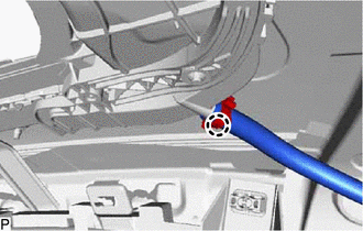
9. DISCONNECT SLIDING ROOF DRAIN HOSE
| (a) for Clamp Type: (1) Disengage the claw and disconnect the sliding roof drain hose. HINT: Use the same procedure for the other 3 sliding roof drain hoses. |
|
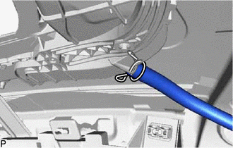
| (b) for Clip Type: (1) Expand the clip and disconnect the sliding roof drain hose. HINT: Use the same procedure for the other 3 sliding roof drain hoses. |
|
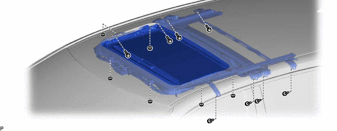
10. REMOVE SLIDING ROOF HOUSING ASSEMBLY
(a) Remove the 8 bolts, 6 nuts and sliding roof housing assembly.
 Components
COMPONENTS ILLUSTRATION *1 SLIDING ROOF DRIVE GEAR SUB-ASSEMBLY *2 MAP LIGHT ASSEMBLY *3 MAP LIGHT BRACKET - - N*m (kgf*cm, ft.*lbf): Specified torque MP grease ILLU ...
 Disassembly
DISASSEMBLY PROCEDURE 1. REMOVE SLIDING ROOF DRIVE GEAR SUB-ASSEMBLY (a) Remove the bolt. Remove in this Direction (b) Disengage the 2 guides as shown in the illustration to remove the map l ...
Other materials:
Lexus RX (RX 350L, RX450h) 2016-2026 Repair Manual > Automatic Transaxle System: Shift Solenoid "A" Actuator Stuck On (P07507E)
DESCRIPTION Based on signals from the transmission revolution sensors (NT, NC3 and NC), the actual gear is detected. The ECM compares the actual gear with the shift schedule in the ECM memory to detect mechanical malfunctions of the shift solenoid valves, transmission valve body assembly and automat ...
Lexus RX (RX 350L, RX450h) 2016-2026 Repair Manual > Fuel Pressure Sensor (for High Pressure): Removal
REMOVAL CAUTION / NOTICE / HINT The necessary procedures (adjustment, calibration, initialization or registration) that must be performed after parts are removed and installed, or replaced during fuel pressure sensor removal/installation are shown below. Necessary Procedures After Parts Removed/Inst ...
Lexus RX (RX 350L, RX450h) 2016-{YEAR} Owners Manual
- For your information
- Pictorial index
- For safety and security
- Instrument cluster
- Operation of each component
- Driving
- Lexus Display Audio system
- Interior features
- Maintenance and care
- When trouble arises
- Vehicle specifications
- For owners
Lexus RX (RX 350L, RX450h) 2016-{YEAR} Repair Manual

0.0096