Lexus RX (RX 350L, RX450h) 2016-2026 Repair Manual: Rear Power Window Switch
Components
COMPONENTS
ILLUSTRATION
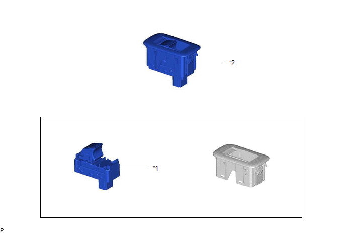
| *1 | REAR POWER WINDOW REGULATOR SWITCH ASSEMBLY | *2 | REAR POWER WINDOW REGULATOR SWITCH ASSEMBLY WITH REAR DOOR UPPER ARMREST BASE PANEL |
Inspection
INSPECTION
PROCEDURE
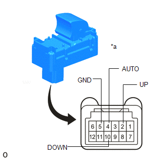
1. INSPECT REAR POWER WINDOW REGULATOR SWITCH ASSEMBLY (for LH/RH DOOR)
| (a) Check the switch function. (1) Measure the resistance according to the value(s) in the table below. Standard Resistance:
If the result is not as specified, replace the power window regulator switch assembly. |
|
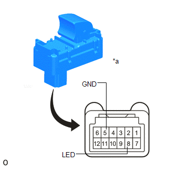
| (b) Check that the LED illuminates. (1) Apply battery voltage to the power window regulator switch assembly and check that the LED illuminates. OK:
If the result is not as specified, replace the power window regulator switch assembly. |
|
Removal
REMOVAL
CAUTION / NOTICE / HINT
HINT:
- Use the same procedure for the RH side and LH side.
- The following procedure is for the LH side.
PROCEDURE
1. REMOVE REAR POWER WINDOW REGULATOR SWITCH ASSEMBLY WITH REAR DOOR UPPER ARMREST BASE PANEL
Click here .gif)
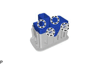
2. REMOVE REAR POWER WINDOW REGULATOR SWITCH ASSEMBLY
| (a) Disengage the 4 claws to remove the rear power window regulator switch assembly. |
|
Installation
INSTALLATION
CAUTION / NOTICE / HINT
HINT:
- Use the same procedure for the RH side and LH side.
- The following procedure is for the LH side.
PROCEDURE
1. INSTALL REAR POWER WINDOW REGULATOR SWITCH ASSEMBLY
(a) Engage the 4 claws to install the rear power window regulator switch assembly.
2. INSTALL REAR POWER WINDOW REGULATOR SWITCH ASSEMBLY WITH REAR DOOR UPPER ARMREST BASE PANEL
Click here .gif)
 Removal
REMOVAL CAUTION / NOTICE / HINT The necessary procedures (adjustment, calibration, initialization or registration) that must be performed after parts are removed and installed, or replaced during quar ...

Other materials:
Lexus RX (RX 350L, RX450h) 2016-2026 Repair Manual > Air Conditioning Filter: Removal
REMOVAL PROCEDURE 1. REMOVE GLOVE COMPARTMENT DOOR ASSEMBLY (a) Disengage the claw to disconnect the glove compartment door stopper sub-assembly. *1 Glove Compartment Door Stopper Sub-assembly *a Stopper (b) Slightly bend stoppers (A) and (B) in the directions indica ...
Lexus RX (RX 350L, RX450h) 2016-2026 Repair Manual > Fuel Pump (for Tmmc Made): Components
COMPONENTS ILLUSTRATION *1 REAR DOOR SCUFF PLATE LH *2 UPPER QUARTER TRIM PAD LH *3 REAR SEAT SIDE GARNISH LH - - ILLUSTRATION *1 REAR DOOR SCUFF PLATE RH *2 UPPER QUARTER TRIM PAD RH *3 REAR SEAT SIDE GARNISH RH - - ILLUSTRATION *1 FRONT FLOOR CAR ...
Lexus RX (RX 350L, RX450h) 2016-{YEAR} Owners Manual
- For your information
- Pictorial index
- For safety and security
- Instrument cluster
- Operation of each component
- Driving
- Lexus Display Audio system
- Interior features
- Maintenance and care
- When trouble arises
- Vehicle specifications
- For owners
Lexus RX (RX 350L, RX450h) 2016-{YEAR} Repair Manual

0.0116