Lexus RX (RX 350L, RX450h) 2016-2026 Repair Manual: Rear Window Defogger System does not Operate
DESCRIPTION
When the rear window defogger switch on the radio receiver assembly is pressed, the operation signal is transmitted to the air conditioning amplifier assembly via CAN communication. When the air conditioning amplifier assembly receives the signal, it turns on the semiconductor pwr integration ECU to operate the window defogger system.
WIRING DIAGRAM
.png)
CAUTION / NOTICE / HINT
NOTICE:
- Inspect the fuses for circuits related to this system before performing the following procedure.
-
If the battery voltage is low, the window defogger system may not operate. When "Operation of Electrical Items Restricted." is not displayed on the multi-information display in the combination meter assembly, check the Data List item "Battery Control Count (Body ECU)".
Click here
.gif)
- The window defogger system uses the CAN communication. First, confirm that there is nomalfunction in the CAN communication line. Refer to How to Proceed with Troubleshooting.
PROCEDURE
| 1. | CHECK AIR CONDITIONING SYSTEM |
(a) Check the air conditioning system.
HINT:
Both the window defogger system operation signal and air conditioning system operation signal are transmitted to the air conditioning amplifier assembly through the same communication line.
OK:
The air conditioning system operates normally.
| NG | .gif) | GO TO AIR CONDITIONING SYSTEM |
|
.gif)
| 2. | PERFORM ACTIVE TEST USING TECHSTREAM |
(a) Connect the Techstream to the DLC3.
(b) Turn the engine switch on (IG).
(c) Turn the Techstream on.
(d) Enter the following menus: Body Electrical / Air Conditioner / Active Test.
(e) Perform the Active Test according to the display on the Techstream.
Body Electrical > Air Conditioner > Active Test| Tester Display | Measurement Item | Control Range | Diagnostic Note |
|---|---|---|---|
| Defogger Relay (Rear) | Rear window defogger wire (back window glass) | OFF or ON | - |
| Tester Display |
|---|
| Defogger Relay (Rear) |
OK:
The rear window defogger system operates normally.
| NG | | GO TO STEP 4 |
|
| 3. | REPLACE AIR CONDITIONING AMPLIFIER ASSEMBLY |
(a) Replace the air conditioning amplifier assembly with a new or known good one.
Click here
(b) Check that the window defogger system operates normally.
Click here
OK:
The window defogger system operates normally.
| OK | | END (AIR CONDITIONING AMPLIFIER ASSEMBLY WAS DEFECTIVE) |
| NG | | REPLACE RADIO RECEIVER ASSEMBLY |
| 4. | CHECK SEMICONDUCTOR POWER INTEGRATION ECU |
(a) Using a voltmeter, check the signal reading of the semiconductor pwr integration ECU.
Click here
OK:
Output signal reading is normal.
| NG | | INSPECT SEMICONDUCTOR POWER INTEGRATION ECU (RESULTS OF SIGNAL READING CHECK) |
|
| 5. | CHECK HARNESS AND CONNECTOR (SEMICONDUCTOR PWR INTEGRATION ECU POWER SOURCE AND BODY GROUND) |
(a) Remove the semiconductor pwr integration ECU from the engine room relay block.
Click here
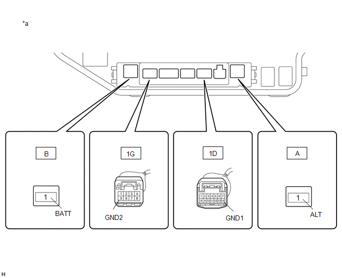
| *a | Component without semiconductor pwr integration ECU (Engine Room Relay Block) | - | - |
(b) Measure the voltage according to the value(s) in the table below.
Standard Voltage:
| Tester Connection | Condition | Specified Condition |
|---|---|---|
| B-1 (BATT) - Body ground | Always | 11 to 14 V |
| A-1 (ALT) - Body ground | Always | 11 to 14 V |
(c) Measure the resistance according to the value(s) in the table below.
Standard Resistance:
| Tester Connection | Condition | Specified Condition |
|---|---|---|
| 1D-14 (GND1) - Body ground | Always | Below 1 Ω |
| 1G-5 (GND2) - Body ground | Always | Below 1 Ω |
| NG | | REPAIR OR REPLACE HARNESS OR CONNECTOR |
|
| 6. | CHECK HARNESS AND CONNECTOR (SEMICONDUCTOR PWR INTEGRATION ECU - AIR CONDITIONING AMPLIFIER ASSEMBLY) |
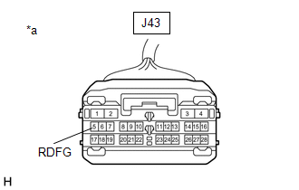
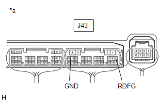
(a) Disconnect the J43 air conditioning amplifier assembly connector.
(b) Measure the resistance according to the value(s) in the table below.
Standard Resistance:
| Tester Connection | Condition | Specified Condition |
|---|---|---|
| J43-5 (RDFG) - 1D-5 (-S) | Always | Below 1 Ω |
| J43-5 (RDFG) or 1D-5 (-S) - Body ground | Always | 10 kΩ or higher |
| NG | | REPAIR OR REPLACE HARNESS OR CONNECTOR |
|
| 7. | CHECK SEMICONDUCTOR POWER INTEGRATION ECU |
(a) Install the semiconductor pwr integration ECU.
Click here
| (b) Measure the voltage according to the value(s) in the table below. Standard Voltage:
|
|
| NG | | REPLACE SEMICONDUCTOR POWER INTEGRATION ECU |
|
| 8. | CHECK AIR CONDITIONING AMPLIFIER ASSEMBLY |
(a) Reconnect the J43 air conditioning amplifier assembly connector.
| (b) Measure the voltage according to the value(s) in the table below. Standard Voltage:
|
|
| NG | | REPLACE AIR CONDITIONING AMPLIFIER ASSEMBLY |
|
| 9. | CHECK HARNESS AND CONNECTOR (SEMICONDUCTOR PWR INTEGRATION ECU - REAR WINDOW DEFOGGER WIRE (BACK WINDOW GLASS)) |
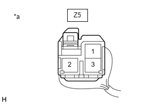
(a) Disconnect the Z5 rear window defogger wire (back window glass) connector.
(b) Disconnect the 1C semiconductor pwr integration ECU connector.
(c) Measure the resistance according to the value(s) in the table below.
Standard Resistance:
| Tester Connection | Condition | Specified Condition |
|---|---|---|
| 1C-1 (L) - Z5-1 | Always | Below 1 Ω |
| NG | | REPAIR OR REPLACE HARNESS OR CONNECTOR |
|
| 10. | CHECK SEMICONDUCTOR POWER INTEGRATION ECU |
(a) Reconnect the 2C semiconductor pwr integration ECU connector.
| (b) Measure the voltage according to the value(s) in the table below. Standard Voltage:
|
|
| NG | | REPLACE SEMICONDUCTOR POWER INTEGRATION ECU |
|
| 11. | CHECK HARNESS AND CONNECTOR (REAR WINDOW DEFOGGER WIRE (BACK WINDOW GLASS) - BODY GROUND) |
(a) Disconnect the Z13 rear window defogger wire (back window glass) connector.
(b) Measure the resistance according to the value(s) in the table below.
Standard Resistance:
| Tester Connection | Condition | Specified Condition |
|---|---|---|
| Z13-1 - Body ground | Always | Below 1 Ω |
| OK | | REPAIR OR REPLACE REAR WINDOW DEFOGGER WIRE (BACK WINDOW GLASS) |
| NG | | REPAIR OR REPLACE HARNESS OR CONNECTOR |
 Diagnosis System
DIAGNOSIS SYSTEM CHECK DLC3 (a) Check the DLC3. Click here INSPECT BATTERY VOLTAGE (a) Measure the battery voltage. Standard Voltage: 11 to 14 V If the voltage is below 11 V, recharge or replace th ...
 Window Defogger Wire
On-vehicle InspectionON-VEHICLE INSPECTION PROCEDURE 1. CHECK REAR WINDOW DEFOGGER OPERATION (a) When the engine switch is ON and the rear window defogger switch is pressed, check that the window defo ...
Other materials:
Lexus RX (RX 350L, RX450h) 2016-2026 Repair Manual > Towing Converter System: System Description
SYSTEM DESCRIPTION INPUT SIGNAL Item Detail Stop lights Receives a stop light signal from the stop light switch via direct line. Turn indicator lights Receives turn indicator light signals from the turn signal flasher via direct line. Taillights Receives a taillight signal fro ...
Lexus RX (RX 350L, RX450h) 2016-2026 Repair Manual > Navigation Ecu: Removal
REMOVAL CAUTION / NOTICE / HINT The necessary procedures (adjustment, calibration, initialization, or registration) that must be performed after parts are removed and installed, or replaced during navigation ECU removal/installation are shown below. Necessary Procedures After Parts Removed/Installed ...
Lexus RX (RX 350L, RX450h) 2016-{YEAR} Owners Manual
- For your information
- Pictorial index
- For safety and security
- Instrument cluster
- Operation of each component
- Driving
- Lexus Display Audio system
- Interior features
- Maintenance and care
- When trouble arises
- Vehicle specifications
- For owners
Lexus RX (RX 350L, RX450h) 2016-{YEAR} Repair Manual

0.0103