Lexus RX (RX 350L, RX450h) 2016-2026 Repair Manual: Terminals Of Ecu
TERMINALS OF ECU
CHECK INSTRUMENT PANEL JUNCTION BLOCK ASSEMBLY AND MAIN BODY ECU (MULTIPLEX NETWORK BODY ECU)
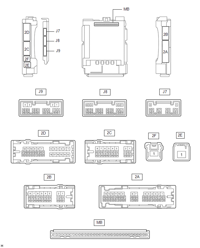
(a) Remove the main body ECU (multiplex network body ECU) from the instrument panel junction block assembly.
Click here .gif)
(b) Reconnect the instrument panel junction block assembly connector.
(c) Measure the voltage and resistance according to the value(s) in the table below.
| Tester Connection | Wiring Color | Terminal Description | Condition | Specified Condition |
|---|---|---|---|---|
| MB-11 (GND1) - Body ground | - | Ground | Always | Below 1 Ω |
| MB-30 (ACC) - Body ground | - | ACC power supply | Engine switch on (ACC) | 11 to 14 V |
| MB-30 (ACC) - Body ground | - | ACC power supply | Engine switch off | Below 1 V |
| MB-31 (BECU) - Body ground | - | Battery power supply | Always | 11 to 14 V |
| MB-32 (IG) - Body ground | - | IG power supply | Engine switch on (IG) | 11 to 14 V |
| MB-32 (IG) - Body ground | - | IG power supply | Engine switch off | Below 1 V |
(d) Install the main body ECU (multiplex network body ECU) to the instrument panel junction block assembly.
Click here
(e) Measure the voltage and check for pulses according to the value(s) in the table below.
| Tester Connection | Wiring Color | Terminal Description | Condition | Specified Condition |
|---|---|---|---|---|
| J9-2 (LSWR) - Body ground | L - Body ground | Rear door RH unlock detection switch input | Rear door RH unlocked | Below 1 V |
| J9-2 (LSWR) - Body ground | L - Body ground | Rear door RH unlock detection switch input | Rear door RH locked | Pulse generation |
| J8-2 (UL3) - Body ground | V - Body ground | Driver door key-linked unlock input | Driver door key cylinder turned to neutral position → on (unlock) | Pulse generation → Below 1 V |
| J8-6 (FLCY) - Body ground | P - Body ground | Front door courtesy light switch (for LH) input | Front door LH open | Below 1 V |
| J8-6 (FLCY) - Body ground | P - Body ground | Front door courtesy light switch (for LH) input | Front door LH closed | Pulse generation |
| J8-27 (FRCY) - Body ground | R - Body ground | Front door courtesy light switch (for RH) input | Front door RH open | Below 1 V |
| J8-27 (FRCY) - Body ground | R - Body ground | Front door courtesy light switch (for RH) input | Front door RH closed | Pulse generation |
| J8-29 (L2) - Body ground | P - Body ground | Driver door key-linked lock input | Driver door key cylinder turned to neutral position → on (lock) | Pulse generation → Below 1 V |
| 2D-8 (ACT-) - Body ground | W - Body ground | Door lock motor unlock drive output | Door control switch or driver door key cylinder off → on (unlock) | Below 1 V → 11 to 14 V → Below 1 V |
| 2D-6 (ACT+) - Body ground | P - Body ground | Door lock motor lock drive output | Door control switch or driver door key cylinder off → on (lock) | Below 1 V → 11 to 14 V → Below 1 V |
| 2D-24 (LCTY) - Body ground | W - Body ground | Rear door courtesy light switch (for LH) input | Rear door LH open | Below 1 V |
| 2D-24 (LCTY) - Body ground | W - Body ground | Rear door courtesy light switch (for LH) input | Rear door LH closed | Pulse generation |
| 2B-14 (LSWL) - Body ground | V - Body ground | Rear door LH unlock detection switch input | Rear door LH unlocked | Below 1 V |
| 2B-14 (LSWL) - Body ground | V - Body ground | Rear door LH unlock detection switch input | Rear door LH locked | Pulse generation |
| 2B -1 (ACT-) - Body ground | B - Body ground | Door lock motor unlock drive output | Door control switch or driver door key cylinder off → on (unlock) | Below 1 V → 11 to 14 V → Below 1 V |
| 2D-9 (ACT-) - Body ground | B - Body ground | Door lock motor unlock drive output | Door control switch or driver door key cylinder off → on (unlock) | Below 1 V → 11 to 14 V → Below 1 V |
| 2B-4 (ACTD) - Body ground | B - Body ground | Door lock motor unlock drive output | Door control switch or driver door key cylinder off → on (unlock) | Below 1 V → 11 to 14 V → Below 1 V |
| 2D-18 (ACT+) - Body ground | B - Body ground | Door lock motor lock drive output | Door control switch or driver door key cylinder off → on (lock) | Below 1 V → 11 to 14 V → Below 1 V |
| 2B-2 (ACT+) - Body ground | R - Body ground | Door lock motor lock drive output | Door control switch or driver door key cylinder off → on (lock) | Below 1 V → 11 to 14 V → Below 1 V |
| 2A-31 (RCTY) - Body ground | R - Body ground | Rear door courtesy light switch (for RH) input | Rear door RH open | Below 1 V |
| 2A-31 (RCTY) - Body ground | R - Body ground | Rear door courtesy light switch (for RH) input | Rear door RH closed | Pulse generation |
| 2B-12 (LSFR) - Body ground | P - Body ground | Front door RH unlock detection switch input | Front door RH unlocked | Below 1 V |
| 2B-12 (LSFR) - Body ground | P - Body ground | Front door RH unlock detection switch input | Front door RH locked | Pulse generation |
| 2B-13 (LSFL) - Body ground | B - Body ground | Front door LH unlock detection switch input | Front door LH unlocked | Below 1 V |
| 2B-13 (LSFL) - Body ground | B - Body ground | Front door LH unlock detection switch input | Front door LH locked | Pulse generation |
| 2B-16 (L1) - Body ground | B - Body ground | Door control switch assembly input | Door control switch assembly off → on (lock) | Pulse generation → Below 1 V |
| 2A-7 (GSW) - Body ground | B - Body ground | Unlock detection input | Engine switch on (IG) | 2.8 to 4.3 V |
| 2A-39 (UL1) - Body ground | GR - Body ground | Door control switch assembly input | Door control switch assembly off → on (unlock) | Pulse generation → Below 1 V |
CHECK CERTIFICATION ECU (SMART KEY ECU ASSEMBLY)
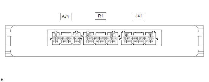
(a) Disconnect the J41 certification ECU (smart key ECU assembly) connector.
(b) Measure the voltage and resistance according to the value(s) in the table below.
| Tester Connection | Wiring Color | Terminal Description | Condition | Specified Condition |
|---|---|---|---|---|
| J41-4 (+B) - Body ground | V - Body ground | Battery power supply | Always | 11 to 14 V |
| J41-18 (E) - Body ground | W-B - Body ground | Ground | Always | Below 1 Ω |
(c) Reconnect the J41 certification ECU (smart key ECU assembly) connector.
(d) Check for pulses according to the value(s) in the table below.
| Tester Connection | Wiring Color | Terminal Description | Condition | Specified Condition |
|---|---|---|---|---|
| R1-26 (TSW5) - Body ground | G - Body ground | Back door opener switch input | Back door opener switch assembly (open switch) off → on | Pulse generation |
| R1-27 (TSW6) - Body ground | L - Body ground | Back door opener switch input | Back door opener switch assembly (lock switch) off → on | Pulse generation |
CHECK AIRBAG SENSOR ASSEMBLY
Click here
 Problem Symptoms Table
PROBLEM SYMPTOMS TABLE HINT:
Use the table below to help determine the cause of problem symptoms. If multiple suspected areas are listed, the potential causes of the symptoms are listed in order of ...
 Data List / Active Test
DATA LIST / ACTIVE TEST DATA LIST HINT: Using the Techstream to read the Data List allows the values or states of switches, sensors, actuators and other items to be read without removing any parts. Th ...
Other materials:
Lexus RX (RX 350L, RX450h) 2016-2026 Repair Manual > Steering Heater Switch: Inspection
INSPECTION PROCEDURE 1. INSPECT STEERING HEATER SWITCH (INTEGRATION CONTROL AND PANEL ASSEMBLY) (a) Measure the voltage according to the value (s) in the table below. Standard Voltage: Tester Connection (Positive (+) Tester Probe - Negative (-) Tester Probe) Switch Condition Specified Con ...
Lexus RX (RX 350L, RX450h) 2016-2026 Repair Manual > Vehicle Stability Control System: Yaw Rate Sensor Signal Compare Failure (C124F62)
DESCRIPTION for Optitron Meter Type:
This DTC is stored when the skid control ECU (brake actuator assembly) detects improper installation of the yaw rate sensor (airbag sensor assembly) or an abnormality in the difference between the yaw rate sensor value and the control value estimated based on ...
Lexus RX (RX 350L, RX450h) 2016-{YEAR} Owners Manual
- For your information
- Pictorial index
- For safety and security
- Instrument cluster
- Operation of each component
- Driving
- Lexus Display Audio system
- Interior features
- Maintenance and care
- When trouble arises
- Vehicle specifications
- For owners
Lexus RX (RX 350L, RX450h) 2016-{YEAR} Repair Manual

0.0125