Lexus RX (RX 350L, RX450h) 2016-2026 Repair Manual: Removal
REMOVAL
CAUTION / NOTICE / HINT
The necessary procedures (adjustment, calibration, initialization, or registration) that must be performed after parts are removed and installed, or replaced during blower unit removal/installation are shown below.
Necessary Procedure After Parts Removed/Installed/Replaced| Replaced Part or Performed Procedure | Necessary Procedure | Effect/Inoperative Function when Necessary Procedure not Performed | Link |
|---|---|---|---|
|
*1: When performing learning using the Techstream.
Click here | |||
| Disconnect cable from negative battery terminal | Memorize steering angle neutral point | Lane Control System | |
| Pre-collision System | |||
| Intelligent Clearance Sonar System*1 | |||
| Parking Assist Monitor System | | ||
| Panoramic View Monitor System | | ||
| Lighting System (w/ Automatic Headlight Beam Level Control System) | | ||
| Initialize back door lock | Power Door Lock Control System | | |
| Reset back door close position | Power Back Door System (w/ Outside Door Control Switch) | | |
| Removal/installation of the spiral cable with sensor sub-assembly |
| Parking assist monitor system | |
| Steering angle neutral point (Initialize panoramic view monitor system) | Panoramic view monitor system | | |
| Steering angle neutral point (Initialize intelligent clearance sonar system) | Intelligent clearance sonar system | | |
| No. 1 blower damper servo sub-assembly | Initialization servo motor (Air conditioning system) | DTCs are output | |
HINT:
Before removing the blower assembly, set the air conditioning to recirculation mode.
PROCEDURE
1. PRECAUTION
NOTICE:
Make sure to perform initialization after replacing the No. 1 blower damper servo sub-assembly. If initialization is not performed, the air conditioner unit assembly will not perform properly as the air conditioning amplifier assembly will not be able to recognize the position of the No. 1 blower damper servo sub-assembly.
2. REMOVE AIR CONDITIONER UNIT ASSEMBLY
Click here .gif)
3. REMOVE NO. 5 AIR DUCT SUB-ASSEMBLY
Click here
4. REMOVE BLOWER ASSEMBLY
(a) Disconnect the connector.
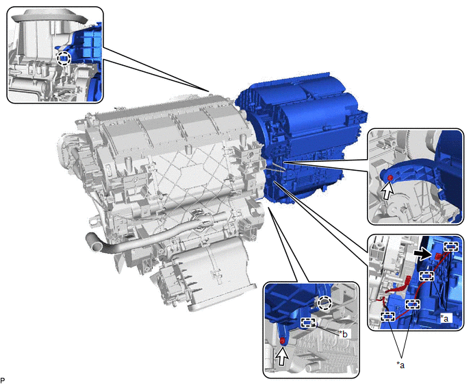
| *a | Guide (A) | *b | Guide (B) |
.png) | Connector | .png) | Screw |
(b) Disengage 4 guides (A).
(c) Remove the 2 screws.
(d) Disengage the 2 claws and guide (B) and remove the blower assembly from the air conditioning radiator assembly.
5. REMOVE AIR FILTER COVER PLATE
(a) Disengage the claw and 2 guides as indicated by the arrows, in the order shown in the illustration to remove the air filter cover plate.
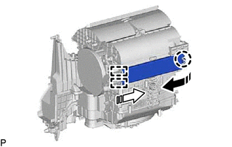
.png) | Remove in this Direction (1) |
.png) | Remove in this Direction (2) |
6. REMOVE CLEAN AIR FILTER
(a) Remove the air filter sub-assembly as shown in the illustration.
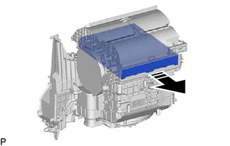
| | Remove in this Direction |
| (b) Disengage the 4 guides to remove the clean air filter from the air filter case. |
|
.png)
 Components
COMPONENTS ILLUSTRATION *1 AIR FILTER COVER PLATE *2 BLOWER ASSEMBLY *3 BLOWER MOTOR WITH FAN SUB-ASSEMBLY *4 CLEAN AIR FILTER *5 NO. 1 BLOWER DAMPER SERVO SUB-ASSEMBLY *6 ...
 Disassembly
DISASSEMBLY PROCEDURE 1. PRECAUTION NOTICE: Make sure to perform initialization after replacing the No. 1 blower damper servo sub-assembly. If initialization is not performed, the air conditioner unit ...
Other materials:
Lexus RX (RX 350L, RX450h) 2016-2026 Repair Manual > Audio And Visual System (for 8 Inch Display): Lost Communication with Haptic Device (B1323-B1326)
DESCRIPTION These DTCs are stored when communication between the radio receiver assembly and remote touch (remote operation controller assembly), combination meter assembly, headup display (meter mirror sub-assembly)* or clock assembly is not possible.
*: w/ Headup Display System
DTC No. ...
Lexus RX (RX 350L, RX450h) 2016-2026 Repair Manual > Steering Column Assembly: Reassembly
REASSEMBLY CAUTION / NOTICE / HINT NOTICE:
Do not drop the power steering ECU assembly, strike it with tools or subject it to impacts.
If the power steering ECU assembly is subjected to an impact, replace it with a new one.
Do not pull the wire harness.
Do not allow any moisture to come int ...
Lexus RX (RX 350L, RX450h) 2016-{YEAR} Owners Manual
- For your information
- Pictorial index
- For safety and security
- Instrument cluster
- Operation of each component
- Driving
- Lexus Display Audio system
- Interior features
- Maintenance and care
- When trouble arises
- Vehicle specifications
- For owners
Lexus RX (RX 350L, RX450h) 2016-{YEAR} Repair Manual

0.0138