Lexus RX (RX 350L, RX450h) 2016-2026 Repair Manual: Main Switch Circuit
DESCRIPTION
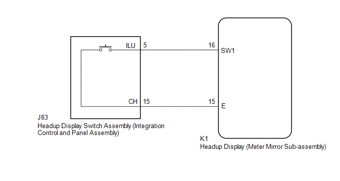
The headup display switch assembly (integration control and panel assembly) and headup display (meter mirror sub-assembly) are connected via direct line. The headup display (meter mirror sub-assembly) can be turned off and on by operating the headup display switch assembly (integration control and panel assembly).
WIRING DIAGRAM
PROCEDURE
| 1. | READ VALUE USING TECHSTREAM (MAIN SWITCH) |
(a) Connect the Techstream to the DLC3.
(b) Turn the engine switch on (IG).
(c) Turn the Techstream on.
(d) Enter the following menus: Body Electrical / Head Up Display / Data List.
(e) Read the Data List according to the display on the Techstream.
Body Electrical > Head Up Display > Data List| Tester Display | Measurement Item | Range | Normal Condition | Diagnostic Note |
|---|---|---|---|---|
| Main Switch | Headup display switch assembly | OFF or ON | OFF: Switch released ON: Switch pushed | - |
| Tester Display |
|---|
| Main Switch |
OK:
Headup display switch assembly condition displayed on the Techstream changes with the actual switch operation.
| OK | .gif) | REPLACE HEADUP DISPLAY (METER MIRROR SUB-ASSEMBLY) |
|
.gif)
| 2. | INSPECT HEADUP DISPLAY SWITCH ASSEMBLY (INTEGRATION CONTROL AND PANEL ASSEMBLY) |
(a) Remove the integration control and panel assembly.
Click here .gif)
(b) Inspect the integration control and panel assembly.
Click here
| NG | | REPLACE INTEGRATION CONTROL AND PANEL ASSEMBLY |
|
| 3. | CHECK HARNESS AND CONNECTOR (HEADUP DISPLAY (METER MIRROR SUB-ASSEMBLY) - INTEGRATION CONTROL AND PANEL ASSEMBLY) |
(a) Disconnect the K1 headup display (meter mirror sub-assembly) connector.
(b) Measure the resistance according to the value(s) in the table below.
Standard Resistance:
| Tester Connection | Condition | Specified Condition |
|---|---|---|
| K1-16 (SW1) - J83-5 (ILU) | Always | Below 1 Ω |
| K1-15 (E) - J83-15 (CH) | Always | Below 1 Ω |
| K1-16 (SW1) or J83-5 (ILU) - Body ground | Always | 10 kΩ or higher |
| K1-15 (E) or J83-15 (CH) - Body ground | Always | 10 kΩ or higher |
| OK | | REPLACE HEADUP DISPLAY (METER MIRROR SUB-ASSEMBLY) |
| NG | | REPAIR OR REPLACE HARNESS OR CONNECTOR |
 Lost Communication with ECM / PCM "A" (U0100,U0142,U0163,U023A)
DESCRIPTION The headup display (meter mirror sub-assembly) communicates with the ECM, main body ECU (multiplex network body ECU), radio receiver assembly and forward recognition camera via CAN communi ...

Other materials:
Lexus RX (RX 350L, RX450h) 2016-2026 Repair Manual > Wireless Charging System: Parts Location
PARTS LOCATION ILLUSTRATION *1 INSTRUMENT PANEL JUNCTION BLOCK ASSEMBLY - ECU-ACC FUSE - PANEL FUSE *2 MOBILE WIRELESS CHARGER CRADLE ASSEMBLY *3 ENGINE ROOM RELAY BLOCK AND JUNCTION BLOCK ASSEMBLY - RADIO NO. 1 FUSE *4 CERTIFICATION ECU (SMART KEY ECU ASSEMBLY) *5 COMBINAT ...
Lexus RX (RX 350L, RX450h) 2016-2026 Repair Manual > Air Conditioning System: Pressure Sensor Circuit (B1423/23)
DESCRIPTION This DTC is stored if refrigerant pressure on the high pressure side is extremely low (196 kPa (2.0 kgf/cm2, 28 psi) or less) or extremely high (2812 kPa (28.7 kgf/cm2, 408 psi) or more). The air conditioner pressure sensor, which is installed to the high pressure side pipe to detect ref ...
Lexus RX (RX 350L, RX450h) 2016-{YEAR} Owners Manual
- For your information
- Pictorial index
- For safety and security
- Instrument cluster
- Operation of each component
- Driving
- Lexus Display Audio system
- Interior features
- Maintenance and care
- When trouble arises
- Vehicle specifications
- For owners
Lexus RX (RX 350L, RX450h) 2016-{YEAR} Repair Manual

0.013