Lexus RX (RX 350L, RX450h) 2016-2026 Repair Manual: Odo/Trip Switch Malfunction
DESCRIPTION
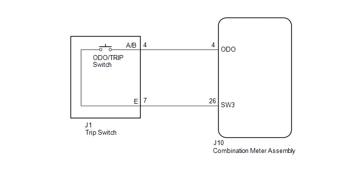
In this circuit, the combination meter assembly detects ODO/TRIP switch signals via a direct line.
WIRING DIAGRAM
CAUTION / NOTICE / HINT
NOTICE:
When replacing the combination meter assembly, always replace it with a new one. If a combination meter assembly which was installed to another vehicle is used, the information stored in it will not match the information from the vehicle and a DTC may be stored.
PROCEDURE
| 1. | READ VALUE USING TECHSTREAM (ODO/TRIP CHANGE SW) |
(a) Connect the Techstream to the DLC3.
(b) Turn the engine switch on (IG).
(c) Turn the Techstream on.
(d) Enter the following menus: Body Electrical / Combination Meter / Data List.
(e) Read the Data List according to the display on the Techstream.
Body Electrical > Combination Meter > Data List| Tester Display | Measurement Item | Range | Normal Condition | Diagnostic Note |
|---|---|---|---|---|
| ODO/TRIP Change SW | ODO/TRIP switch | OFF or ON | OFF: Switch released ON: Switch pushed | - |
| Tester Display |
|---|
| ODO/TRIP Change SW |
OK:
ODO/TRIP switch condition displayed on the Techstream changes with the actual switch operation.
| OK | .gif) | REPLACE COMBINATION METER ASSEMBLY |
|
.gif)
| 2. | INSPECT TRIP SWITCH |
(a) Remove the trip switch.
Click here .gif)
(b) Inspect the trip switch.
Click here
| NG | | REPLACE TRIP SWITCH |
|
| 3. | CHECK HARNESS AND CONNECTOR (COMBINATION METER ASSEMBLY - TRIP SWITCH) |
(a) Disconnect the J10 combination meter assembly connector.
(b) Measure the resistance according to the value(s) in the table below.
Standard Resistance:
| Tester Connection | Condition | Specified Condition |
|---|---|---|
| J10-4 (ODO) - J1-4 (A/B) | Always | Below 1 Ω |
| J10-26 (SW3) - J1-7 (E) | Always | Below 1 Ω |
| J10-4 (ODO) or J1-4 (A/B) - Body ground | Always | 10 kΩ or higher |
| J10-26 (SW3) or J1-7 (E) - Body ground | Always | 10 kΩ or higher |
| OK | | REPLACE COMBINATION METER ASSEMBLY |
| NG | | REPAIR OR REPLACE HARNESS OR CONNECTOR |
 Engine Coolant Temperature Receiver Gauge Malfunction
DESCRIPTION In this circuit, the combination meter assembly receives engine coolant temperature signals from the ECM via CAN communication. The combination meter assembly displays the engine coolant t ...
 Operating Light Control Rheostat does not Change Light Brightness
DESCRIPTION The combination meter assembly receives signals from this circuit to adjust the illumination of the combination meter assembly. The combination meter assembly sets the illumination level b ...
Other materials:
Lexus RX (RX 350L, RX450h) 2016-2026 Repair Manual > Navigation System: Mute Signal Circuit between Stereo Component Amplifier and Telematics Transceiver
DESCRIPTION The DCM (telematics transceiver) sends a mute signal to the stereo component amplifier assembly. The stereo component amplifier assembly controls the volume according to the mute signal from the DCM (telematics transceiver). WIRING DIAGRAM CAUTION / NOTICE / HINT NOTICE:
Depending on ...
Lexus RX (RX 350L, RX450h) 2016-2026 Repair Manual > Safety Connect System: Indicator (Red) Circuit Short to Ground (B157011,B157013)
DESCRIPTION This DTC is stored when the DCM (telematics transceiver) detects an open or short in the manual (SOS) switch red indicator circuit of the manual (SOS) switch. The manual (SOS) switch red indicator illuminates for 2 seconds and goes off when the engine switch is turned on (IG). If a malfu ...
Lexus RX (RX 350L, RX450h) 2016-{YEAR} Owners Manual
- For your information
- Pictorial index
- For safety and security
- Instrument cluster
- Operation of each component
- Driving
- Lexus Display Audio system
- Interior features
- Maintenance and care
- When trouble arises
- Vehicle specifications
- For owners
Lexus RX (RX 350L, RX450h) 2016-{YEAR} Repair Manual

0.0125