Lexus RX (RX 350L, RX450h) 2016-2026 Repair Manual: Terminals Of Ecu
TERMINALS OF ECU
NOTICE:
- DTCs may be output when connectors are disconnected during inspection. Therefore, be sure to clear the DTCs using the Techstream once the inspection has been completed.
- Do not apply excessive force to the forward recognition camera connector.

CHECK FORWARD RECOGNITION CAMERA
(a) Measure the voltage and resistance according to the value(s) in the table below.
| Terminal No. (Symbol) | Wiring Color | Terminal Description | Condition | Specified Condition |
|---|---|---|---|---|
| U14-7 (IGB) - U14-10 (GND) | SB - BR | Power source | Engine switch on (IG) | 11 to 14 V |
| Engine switch off | Below 1 V | |||
| U14-10 (GND) - Body ground | BR - Body ground | Ground | Always | Below 1 Ω |
(b) Check for pulses according to the value(s) in the table below.
HINT:
If the waveform is not similar to that shown in the illustration, a malfunction of a CAN bus line, terminating resistor, or the forward recognition camera is suspected.
| Terminal No. (Symbol) | Wiring Color | Terminal Description | Condition | Specified Condition |
|---|---|---|---|---|
| U14-5 (CA1P) - U14-10 (GND) | V - BR | CAN communication signal | Engine switch on (IG) | Pulse generation (See waveform 1) |
| U14-11 (CA1N) - U14-10 (GND) | P - BR | CAN communication signal | Engine switch on (IG) | Pulse generation (See waveform 2) |
| U14-6 (CANH) - U14-10 (GND) | B - BR | CAN communication signal | Engine switch on (IG) | Pulse generation (See waveform 1) |
| U14-12 (CANL) - U14-10 (GND) | W - BR | CAN communication signal | Engine switch on (IG) | Pulse generation (See waveform 2) |
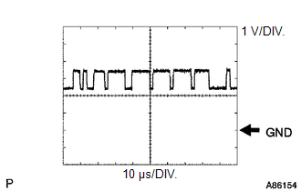
(1) WAVEFORM 1
| Item | Content |
|---|---|
| Terminal Name | Between U14-5 (CA1P) and U14-10 (GND) Between U14-6 (CANH) and U14-10 (GND) |
| Tester Range | 1 V/DIV., 10 μs/DIV. |
| Condition | Engine switch on (IG) |
HINT:
The waveform varies depending on the CAN communication signal.
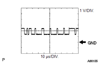
(2) WAVEFORM 2
| Item | Content |
|---|---|
| Terminal Name | Between U14-11 (CA1N) and U14-10 (GND) Between U14-12 (CANL) and U14-10 (GND) |
| Tester Range | 1 V/DIV., 10 μs/DIV. |
| Condition | Engine switch on (IG) |
HINT:
The waveform varies depending on the CAN communication signal.
 Diagnosis System
DIAGNOSIS SYSTEM FUNCTION OF WARNING INDICATOR AND MESSAGE (a) If the pre-collision system is not functioning properly, the driver is warned by the PCS warning light and a warning message is displayed ...
 Dtc Check / Clear
DTC CHECK / CLEAR CHECK DTC (a) Connect the Techstream to the DLC3. (b) Turn the engine switch on (IG). (c) Turn the Techstream on. (d) Enter the following menus: Body Electrical / Pre-Collision Syste ...
Other materials:
Lexus RX (RX 350L, RX450h) 2016-2026 Owners Manual > Rear seats: Second-row seats (RX450h)
Manual seat
Seatback angle adjustment lever
Seat position adjustment lever
Power seat
Seatback angle adjustment switch
Seat position adjustment lever
Second-row seats (RX450hL)
Seatback angle adjustment lever
Seat position adjustment lever
Seatback folding lever
Th ...
Lexus RX (RX 350L, RX450h) 2016-2026 Repair Manual > Lane Control System: Parts Location
PARTS LOCATION ILLUSTRATION *1 MILLIMETER WAVE RADAR SENSOR ASSEMBLY *2 FORWARD RECOGNITION CAMERA *3 SKID CONTROL ECU (BRAKE ACTUATOR ASSEMBLY) *4 ECM *5 POWER STEERING ECU ASSEMBLY - - ILLUSTRATION *A for TFT Meter Type *B for Optitron Meter Type *1 ...
Lexus RX (RX 350L, RX450h) 2016-{YEAR} Owners Manual
- For your information
- Pictorial index
- For safety and security
- Instrument cluster
- Operation of each component
- Driving
- Lexus Display Audio system
- Interior features
- Maintenance and care
- When trouble arises
- Vehicle specifications
- For owners
Lexus RX (RX 350L, RX450h) 2016-{YEAR} Repair Manual

0.0105