Lexus RX (RX 350L, RX450h) 2016-2026 Repair Manual: Inspection
INSPECTION
PROCEDURE
1. INSPECT REAR NO. 2 SEAT OUTER BELT ASSEMBLY RH
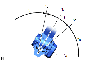
| (a) Before installing the rear No. 2 seat outer belt assembly RH, check the ELR function. NOTICE: Do not disassemble the retractor. (1) Hold the retractor at the angle it would be positioned when it is installed to the vehicle (standard position). Check that the seatbelt can be pulled from the retractor when the angle of the retractor is between 15° forward and 15° rearward of the standard position. Hold the retractor at the angle it would be positioned when it is installed to the vehicle (standard position). Check that the seatbelt locks when the angle of the retractor is 15° or more forward or 15° or more rearward of the standard position. If the result is not as specified, replace the rear No. 2 seat outer belt assembly RH. |
|
2. INSPECT REAR NO. 2 SEAT OUTER BELT ASSEMBLY LH
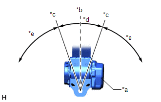
| (a) Before installing the rear No. 2 seat outer belt assembly LH, check the ELR function. NOTICE: Do not disassemble the retractor. (1) Hold the retractor at the angle it would be positioned when it is installed to the vehicle (standard position). Check that the seatbelt can be pulled from the retractor when the angle of the retractor is between 15° forward and 15° rearward of the standard position. Hold the retractor at the angle it would be positioned when it is installed to the vehicle (standard position). Check that the seatbelt locks when the angle of the retractor is 15° or more forward or 15° or more rearward of the standard position. If the result is not as specified, replace the rear No. 2 seat outer belt assembly LH. |
|
 Removal
REMOVAL CAUTION / NOTICE / HINT HINT:
Use the same procedure for the RH side and LH side.
The following procedure is for the LH side.
PROCEDURE 1. REMOVE REAR NO. 2 SEAT ASSEMBLY Click here ...
 Installation
INSTALLATION CAUTION / NOTICE / HINT HINT:
Use the same procedure for the RH side and LH side.
The following procedure is for the LH side.
PROCEDURE 1. INSPECT REAR NO. 2 SEAT OUTER BELT ASSEM ...
Other materials:
Lexus RX (RX 350L, RX450h) 2016-2026 Repair Manual > Immobiliser System: Parts Location
PARTS LOCATION ILLUSTRATION *1 ECM - - ILLUSTRATION *A for Lexus Enform Remote Compatible Type - - *1 ENGINE SWITCH *2 CERTIFICATION ECU (SMART KEY ECU ASSEMBLY) *3 ID CODE BOX (IMMOBILISER CODE ECU) *4 STEERING LOCK ECU (STEERING LOCK ACTUATOR OR UPPER BRA ...
Lexus RX (RX 350L, RX450h) 2016-2026 Repair Manual > Air Fuel Ratio Sensor: Components
COMPONENTS ILLUSTRATION *A for TMC Made *B for TMMC Made *1 AIR FUEL RATIO SENSOR (for Bank 1) *2 AIR FUEL RATIO SENSOR (for Bank 2) *3 NO. 2 ENGINE UNDER COVER *4 NO. 2 EXHAUST MANIFOLD HEAT INSULATOR *5 V-BANK COVER SUB-ASSEMBLY - - N*m (kgf*cm, ft.*l ...
Lexus RX (RX 350L, RX450h) 2016-{YEAR} Owners Manual
- For your information
- Pictorial index
- For safety and security
- Instrument cluster
- Operation of each component
- Driving
- Lexus Display Audio system
- Interior features
- Maintenance and care
- When trouble arises
- Vehicle specifications
- For owners
Lexus RX (RX 350L, RX450h) 2016-{YEAR} Repair Manual

0.0107