Lexus RX (RX 350L, RX450h) 2016-2026 Repair Manual: Short to GND in Immobiliser System Power Source Circuit (B278A)
DESCRIPTION
When there is a short to GND in the power supply for the transponder key amplifier of the engine switch, the certification ECU (smart key ECU assembly) stores this DTC.
| DTC No. | Detection Item | DTC Detection Condition | Trouble Area | Note |
|---|---|---|---|---|
| B278A | Short to GND in Immobiliser System Power Source Circuit | A short to GND in the power supply of the transponder key amplifier of the engine switch (VC5 - VC5) detected. (1 trip detection logic*) |
| DTC output confirmation operation:
|
- *: Only output while a malfunction is present.
| Vehicle Condition when Malfunction Detected | Fail-safe Operation when Malfunction Detected |
|---|---|
| Engine cannot be started when transmitter battery is depleted by holding transmitter near engine switch and pressing and holding engine switch with shift lever in P | - |
| DTC No. | Data List and Active Test |
|---|---|
| B278A | - |
WIRING DIAGRAM
Refer to B2784.
Click here .gif)
CAUTION / NOTICE / HINT
NOTICE:
- When using the Techstream with the engine switch off, connect the Techstream to the DLC3 and turn a courtesy light switch on and off at intervals of 1.5 seconds or less until communication between the Techstream and the vehicle begins. Then select the vehicle type under manual mode and enter the following menus: Body Electrical / Smart Access. While using the Techstream, periodically turn a courtesy light switch on and off at intervals of 1.5 seconds or less to maintain communication between the Techstream and the vehicle.
-
Before replacing the certification ECU (smart key ECU assembly), refer to Registration.
Click here
- After performing repairs, confirm that no DTCs are output by performing "DTC Output Confirmation Operation".
PROCEDURE
| 1. | CHECK CERTIFICATION ECU (SMART KEY ECU ASSEMBLY) |
(a) Using an oscilloscope, check the waveform.
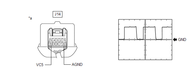
| *a | Component with harness connected (Engine Switch) | - | - |
HINT:
Perform this inspection on the engine switch side.
Measurement Condition:
| Tester Connection | Condition | Tool Setting | Specified Condition |
|---|---|---|---|
| J14-10 (VC5) - J14-6 (AGND) | Engine switch off, electrical key transmitter sub-assembly not in cabin, within 30 seconds of engine switch pressed | 2 V/DIV., 200 ms./DIV. | Pulse generation |
OK:
The waveform is similar to that shown in the illustration.
| OK | .gif) | REPLACE ENGINE SWITCH |
|
.gif)
| 2. | CHECK HARNESS AND CONNECTOR (CERTIFICATION ECU (SMART KEY ECU ASSEMBLY) - ENGINE SWITCH) |
(a) Disconnect the J41 certification ECU (smart key ECU assembly) connector.
(b) Disconnect the J14 engine switch connector.
(c) Measure the resistance according to the value(s) in the table below.
Standard Resistance:
| Tester Connection | Condition | Specified Condition |
|---|---|---|
| J41-7 (VC5) - J14-10 (VC5) | Always | Below 1 Ω |
| J41-11 (AGND) - J14-6 (AGND) | Always | Below 1 Ω |
| J41-7 (VC5) or J14-10 (VC5) - Body ground | Always | 10 kΩ or higher |
| J41-11 (AGND) or J14-6 (AGND) - Body ground | Always | 10 kΩ or higher |
| NG | | REPAIR OR REPLACE HARNESS OR CONNECTOR |
|
| 3. | CHECK CERTIFICATION ECU (SMART KEY ECU ASSEMBLY) |
(a) Reconnect the J41 certification ECU (smart key ECU assembly) connector.
(b) Reconnect the J14 engine switch connector.
(c) Measure the voltage according to the value(s) in the table below.
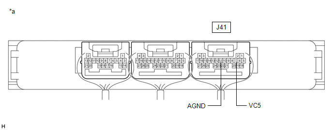
| *a | Component with harness connected (Certification ECU (Smart Key ECU Assembly)) | - | - |
Standard Voltage:
| Tester Connection | Condition | Specified Condition |
|---|---|---|
| J41-7 (VC5) - J41-11 (AGND) | Engine switch off, brake pedal not depressed, 30 seconds or more after driver door opened and then closed | Below 1 V |
| OK | | REPLACE ENGINE SWITCH |
| NG | | REPLACE CERTIFICATION ECU (SMART KEY ECU ASSEMBLY) |
 Engine Starter Communication Malfunction (B2779)
DESCRIPTION If the remote engine start ECU does not respond to the certification ECU (smart key ECU assembly) or the remote engine start ID is not registered, this DTC is stored. HINT: Registration st ...
 Antenna Coil Open / Short (B2784)
DESCRIPTION When an open or short circuit is detected in the transponder key amplifier coil built into the engine switch, the certification ECU (smart key ECU assembly) stores this DTC. This DTC is al ...
Other materials:
Lexus RX (RX 350L, RX450h) 2016-2026 Repair Manual > Lighting System: System Description
SYSTEM DESCRIPTION ILLUMINATED ENTRY SYSTEM (a) The illuminated entry system has the following control functions: Control Outline Lights that Operate Actuation Area-linked When a registered key is brought within any vehicle exterior detection area around the doors, the items listed to t ...
Lexus RX (RX 350L, RX450h) 2016-2026 Repair Manual > Dynamic Torque Control Awd System: Data List / Active Test
DATA LIST / ACTIVE TEST NOTICE: In the table below, the values listed under "Normal Condition" are reference values. Do not depend solely on these reference values when deciding whether a part is faulty or not. HINT: Using the Techstream to read the Data List allows the values or states of switches, ...
Lexus RX (RX 350L, RX450h) 2016-{YEAR} Owners Manual
- For your information
- Pictorial index
- For safety and security
- Instrument cluster
- Operation of each component
- Driving
- Lexus Display Audio system
- Interior features
- Maintenance and care
- When trouble arises
- Vehicle specifications
- For owners
Lexus RX (RX 350L, RX450h) 2016-{YEAR} Repair Manual

0.0134