Lexus RX (RX 350L, RX450h) 2016-2026 Repair Manual: Operation Check
OPERATION CHECK
CHECK SMART ACCESS SYSTEM WITH PUSH-BUTTON START (for Entry Function) OPERATION
NOTICE:
Make sure that the smart access system with push-button start (for Entry Function) has not been canceled before performing this inspection.
(a) Check the entry unlock function (driver door, front passenger door, rear door LH, rear door RH).
(1) Perform a wireless lock door operation to lock the door, touch the unlock sensor built into the backside of the front door outside handle assembly of the driver door while carrying the electrical key transmitter sub-assembly and check that the door unlocks.
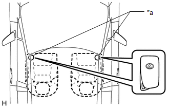
(2) Inspect the entry unlock detection area. Hold the electrical key transmitter sub-assembly at the same height as the door outside handle assembly and approximately 0.7 to 1 m (2.30 to 3.28 ft.) from the vehicle as shown in the illustration and check that the LED (red) of the electrical key transmitter sub-assembly blinks.
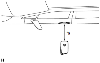
| *a | 0.7 to 1 m (2.30 to 3.28 ft.) |
(3) With the system in unlock standby mode, grasp the front door outside handle assembly (for driver door) and check that the door unlocks.
HINT:
- The system is in unlock standby mode when the electrical key transmitter sub-assembly is in the detection area and the key ID code sent by the electrical key transmitter sub-assembly matches the key ID code stored by the certification ECU (smart key ECU assembly).
- Communication may not be possible if the electrical key transmitter sub-assembly is within 0.2 m (0.656 ft.) of the door outside handle assembly.
- Inspect the front passenger door, rear door LH and rear door RH using the same procedure.
(4) Check the unlock response sensitivity. With the system in unlock standby mode, touch the area shown in the illustration and check that the door unlocks.
NOTICE:
If the sensor is touched too quickly or released too slowly, the sensor may not react and the door will not unlock.
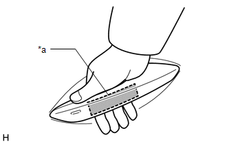
| *a | Unlock Sensor (Backside) |
HINT:
Inspect the front passenger door, rear door LH and rear door RH using the same procedure.
(b) Check the entry lock function (driver door, front passenger door, rear door LH, rear door RH).
NOTICE:
If the electrical key transmitter sub-assembly is in the vehicle but outside the detection area (on the instrument panel, in the glove box, on the floor) and a door lock operation is performed, the key lock-in prevention function will not operate and the electrical key transmitter sub-assembly will be locked inside the vehicle.
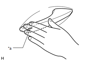
| *a | Lock Sensor |
(1) With the door closed and unlocked, touch the lock sensor of the front door outside handle assembly of the driver door while carrying the electrical key transmitter sub-assembly and check that the door locks.
HINT:
- If the door does not lock even when touching the lock sensor, touch it with your palm.
- Inspect the front passenger door, rear door LH and rear door RH using the same procedure.
(2) Inspect the entry lock operating range. Hold the electrical key transmitter sub-assembly approximately 0.7 to 1 m (2.30 to 3.28 ft.) below the bottom edge of the door glass and approximately 0.3 m (0.984 ft.) from the vehicle as shown in the illustration, touch the lock sensor and check that the door locks.
HINT:
- If the door does not lock even when touching the lock sensor, touch it with your palm.
- As communication may not be possible if the electrical key transmitter sub-assembly is within 0.2 m (0.656 ft.) of the front door outside handle assembly, the door may not lock if the lock sensor is touched with the same hand that is carrying the electrical key transmitter sub-assembly, etc.
- If the key lock-in prevention function buzzer sounds, radio waves from the indoor electrical key antenna may be leaking from the vehicle.
- Inspect the front passenger door, rear door LH and rear door RH using the same procedure.
- The entry lock function cannot be operated more than 3 times consecutively.
| *a | 0.7 to 1 m (2.30 to 3.28 ft.) |
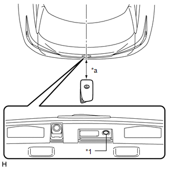
(c) Check the entry back door open function (back door opener switch).
(1) With the back door closed and locked, press the lock switch of the back door opener switch assembly while carrying the electrical key transmitter sub-assembly and check that the back door opens.
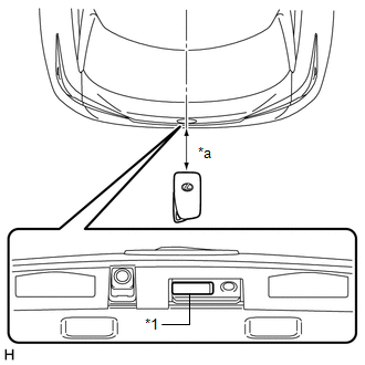
| *1 | Back Door Opener Switch Assembly (Open Switch) |
| *a | 0.7 to 1 m (2.30 to 3.28 ft.) |
(2) Inspect the entry back door open operating range. Hold the electrical key transmitter sub-assembly at the same height as the rear bumper upper surface and approximately 0.7 to 1 m (2.30 to 3.28 ft.) from the vehicle as shown in the illustration, press the open switch of the back door opener switch assembly and check that the back door opens.
(d) Check the entry back door lock function.
NOTICE:
If the electrical key transmitter sub-assembly is in the vehicle but outside the detection area (on the instrument panel, in the glove box or on the floor) and a back door lock operation is performed, the key lock-in prevention function will not operate and the electrical key transmitter sub-assembly will be locked inside the vehicle.
(1) With the back door closed and unlocked, press the lock switch of the back door opener switch assembly while carrying the electrical key transmitter sub-assembly outside of the vehicle and check that the back door locks.
(2) Inspect the entry back door lock operating range. Hold the electrical key transmitter sub-assembly at the same height as the rear bumper upper surface and approximately 0.7 to 1 m (2.30 to 3.28 ft.) from the vehicle as shown in the illustration, press the lock switch of the back door opener switch assembly and check that the back door locks.
| *1 | Back Door Opener Switch Assembly (Lock Switch) |
| *a | 0.7 to 1 m (2.30 to 3.28 ft.) |
HINT:
- Communication may not be possible if the electrical key transmitter sub-assembly is within 0.2 m (0.656 ft.) of the rear bumper.
- If the key lock-in prevention function buzzer sounds, radio waves from the indoor electrical key antenna may be leaking from the vehicle.
(e) Check the hands free power back door function (w/ Hands Free Power Back Door).
(1) Inspect the entry back door open operating range. Hold the electrical key transmitter sub-assembly at the same height as the back door opener switch assembly and approximately 0.7 m (2.30 ft.) from the vehicle as shown in the illustration.
(2) With the back door closed, while carrying the electrical key transmitter sub-assembly, kick your leg so that your foot is 0.1 m (0.328 ft.) or closer to the rear bumper surface. Pull your leg away from the sensor and check that the back door begins to open automatically.
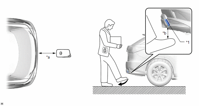
| *1 | Kick Door Control Sensor | - | - |
| *a | Approximately 0.7 m (2.30 ft.) | *b | 0.1 m (0.328 ft.) |
HINT:
-
Refer to Power Back Door System
Click here
.gif)
- Inspect the close function using the same procedure.
(f) Check the hands free close and lock function (w/ Hands Free Power Back Door).
Click here
(g) Check the power back door close and lock function.
(1) With the back door open, press the door control switch while carrying the electrical key transmitter sub-assembly outside of the vehicle and check that the back door closes automatically and then locks.
HINT:
If the door control switch is pressed by a hand which is also holding the electrical key transmitter sub-assembly, the electrical key transmitter sub-assembly may not be detected as in the exterior detection area and the power back door close and lock function may not operate.
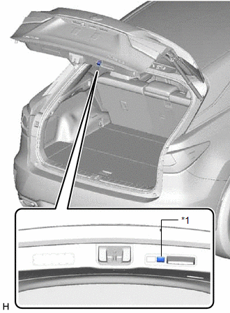
| *1 | Door Control Switch |
| *a | 0.7 to 1 m (2.30 to 3.28 ft.) |
(2) Inspect the power back door close and lock operating range. Hold the electrical key transmitter sub-assembly at the same height as the rear bumper upper surface and approximately 0.7 to 1 m (2.30 to 3.28 ft.) from the vehicle as shown in the illustration, press the door control switch and check that the back door closes automatically and then locks.
(h) Check power back door reservation lock function.
(1) Check that the doors lock after the back door is closed when the lock sensor is operated during the back door closing operation via the power back door function.
(i) Check the key lock-in prevention function (vehicle interior).
NOTICE:
In order to prevent the electrical key transmitter sub-assembly from being locked inside the vehicle, perform this inspection with the window of a door open.
(1) Turn the engine switch off.
(2) Place the electrical key transmitter sub-assembly on a front or rear seat.
(3) Close all of the doors and make sure they are unlocked.
(4) Touch a door lock sensor and check that the doors do not lock and the key lock-in prevention function buzzer (external) sounds for approximately 5 seconds.
(j) Check the transmitter battery saving function
(1) Press the unlock switch of the electrical key transmitter sub-assembly twice while pressing the lock switch and check that the LED of the electrical key transmitter sub-assembly blinks 4 times and enters transmitter battery saving mode.
(2) Check that the smart access system with push-button start (for Entry Function) does not operate while in transmitter battery saving mode.
HINT:
To cancel transmitter battery saving mode, press a switch of the electrical key transmitter sub-assembly.
(k) Check the entry cancel function.
(1) Cancel the smart access system with push-button start and check that all the functions of the smart access system with push-button start (for Entry Function) no longer operate.
Click here
HINT:
While the smart access system with push-button start is canceled, it is possible to lock and unlock the doors with the wireless function, and the engine can be started by holding the electrical key transmitter sub-assembly near the engine switch.
(l) Check the answer-back function (hazard warning light flashing and buzzer sounding).
| Entry Operation | Hazard Warning Light | Wireless Buzzer |
|---|---|---|
| Entry Lock | Flashes once | Sounds once |
| Entry Unlock | Flashes twice | Sounds twice |
KEY DIAGNOSTIC MODE (Using Techstream)
HINT:
- With key diagnostic mode, it is possible to check if the electrical key transmitter sub-assembly is operating properly with the selected electrical key antenna and within the selected detection area by the sounding of the wireless buzzer.
- If the buzzer sounds with [CH1] displayed but not with [CH2], the electrical key transmitter sub-assembly cannot be detected by channel 2 due to a malfunction, such as wave interference.
(a) Enter the following menus: Body Electrical / Smart Access / Utility / Communication Check (Key Diag Mode).
Body Electrical > Smart Access > Utility| Tester Display |
|---|
| Communication Check(Key Diag Mode) |
(b) Inspect the appropriate item according to the following table.
| Tester Display | Inspection Item |
|---|---|
| [CH1/CH2] Overhead + Driver Side*1 | Front door outside handle assembly (electrical key antenna) (for driver door) |
| [CH1] Overhead + Driver Side*1 | |
| [CH2] Overhead + Driver Side*1 | |
| [CH1/CH2] Overhead + Passenger Side*2 | Front door outside handle assembly (electrical key antenna) (for front passenger door) |
| [CH1] Overhead + Passenger Side*2 | |
| [CH2] Overhead + Passenger Side*2 | |
| [CH1/CH2] Overhead + Driver Side Rear*3 | Rear door outside handle assembly (electrical key antenna) (for driver side door) |
| [CH1] Overhead +Driver Side Rear*3 | |
| [CH2] Overhead + Driver Side Rear*3 | |
| [CH1/CH2] Overhead + Passenger Side Rear*4 | Rear door outside handle assembly (electrical key antenna) (for front passenger side door) |
| [CH1] Overhead + Passenger Side Rear*4 | |
| [CH2] Overhead + Passenger Side Rear*4 | |
| [CH1/CH2] Overhead + Front Room*5 | No. 1 indoor electrical key antenna assembly (front floor) |
| [CH1] Overhead + Front Room*5 | |
| [CH2] Overhead + Front Room*5 | |
| [CH1/CH2] Overhead + Rear Room*6 | No. 2 indoor electrical key antenna assembly (rear floor) |
| [CH1] Overhead + Rear Room*6 | |
| [CH2] Overhead + Rear Room*6 | |
| [CH1/CH2] Overhead + Back Door*7 | Electrical key antenna (outside luggage compartment) |
| [CH1] Overhead + Back Door*7 | |
| [CH2] Overhead + Back Door*7 | |
| [CH1/CH2] Luggage + Back Door (inside)*8 | No. 3 indoor electrical key antenna assembly (inside luggage) |
| [CH1] Luggage + Back Door (inside)*8 | |
| [CH2] Luggage + Back Door (inside)*8 | |
| [CH1/CH2] Immobiliser Amp*9 | Amplifier (engine switch) |
| [CH1] Immobiliser Amp*9 | |
| [CH2] Immobiliser Amp*9 |
- [CH1]: Channel 1 is set.
- [CH2]: Channel 2 is set.
-
[CH1/CH2]: Channel 1 and 2 switch automatically at a specific interval*.
*: If the electrical key transmitter sub-assembly is detected with either channel 1 or 2, the buzzer sounds.
(c) Bring the electrical key transmitter sub-assembly near the selected electrical key antenna and check that the wireless buzzer sounds.
HINT:
The buzzer sounds in short, repeated beeps for all items except "Overhead + Rear Room"*6. For "Overhead + Rear Room"*6, the buzzer sounds in one long, continuous beep.
(1) *1: Front door outside handle assembly (for driver door)
| *a | 0.7 to 1 m (2.30 to 3.28 ft.) |
HINT:
- Hold the electrical key transmitter sub-assembly at the same height as the front door outside handle assembly in the position shown in the illustration.
- *2, *3, *4: Perform the same inspection for the front passenger door, rear door LH and rear door RH.
(d) *5: No. 1 indoor electrical key antenna assembly (front floor)
| *a | Inspection Point |
HINT:
Place the electrical key transmitter sub-assembly on the front seat cushion of the driver seat or front passenger seat.
(e) *6: No. 2 indoor electrical key antenna assembly (rear floor)
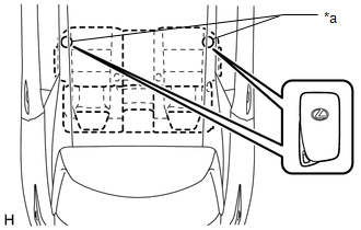
| *a | Inspection Point |
HINT:
Place the electrical key transmitter sub-assembly on the rear seat cushion.
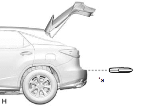
(f) *7: Electrical key antenna (outside luggage compartment)
| *a | 0.7 to 1 m (2.30 to 3.28 ft.) |
HINT:
Hold the electrical key transmitter sub-assembly at the same height as the rear bumper upper surface and align it with the center of the rear of the vehicle as shown in the illustration.
(g) *8: No. 3 indoor electrical key antenna assembly (inside luggage compartment)
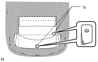
| *a | Inspection Point |
HINT:
Place the electrical key transmitter sub-assembly on the luggage room floor.
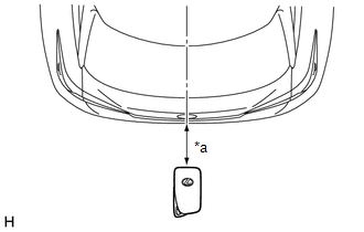
(h) *9: Amplifier (engine switch)

| *1 | Engine Switch |
| *2 | Electrical Key Transmitter Sub-assembly |
HINT:
While facing the logo side of the electrical key transmitter sub-assembly toward the engine switch, hold the transmitter near the engine switch.
 How To Proceed With Troubleshooting
CAUTION / NOTICE / HINT HINT:
Use these procedures to troubleshoot the smart access system with push-button start (for Entry Function).
*: Use the Techstream.
PROCEDURE 1. VEHICLE BROUGH ...
 Customize Parameters
CUSTOMIZE PARAMETERS CUSTOMIZE SMART ACCESS SYSTEM WITH PUSH-BUTTON START (for Entry Function) HINT: The following items can be customized. NOTICE:
When the customer requests a change in a function ...
Other materials:
Lexus RX (RX 350L, RX450h) 2016-2026 Repair Manual > Condenser: Components
COMPONENTS ILLUSTRATION *1 HOOD LOCK ASSEMBLY *2 HOOD LOCK CONTROL CABLE COVER *3 HOOD LOCK RELEASE LEVER PROTECTOR *4 INLET AIR CLEANER ASSEMBLY *5 UPPER RADIATOR SUPPORT SUB-ASSEMBLY - - N*m (kgf*cm, ft.*lbf): Specified torque * For use with a union nut wre ...
Lexus RX (RX 350L, RX450h) 2016-2026 Repair Manual > Rear Power Seat Control System(for Third Row): Fold Seat Switch Circuit
DESCRIPTION When a switch of the fold seat switch assembly or No. 1 fold seat switch assembly is pushed, the fold seat control ECU receives a switch operation signal and operates the fold or return function. WIRING DIAGRAM CAUTION / NOTICE / HINT NOTICE: When a fold seat control ECU (RH/LH seat) is ...
Lexus RX (RX 350L, RX450h) 2016-{YEAR} Owners Manual
- For your information
- Pictorial index
- For safety and security
- Instrument cluster
- Operation of each component
- Driving
- Lexus Display Audio system
- Interior features
- Maintenance and care
- When trouble arises
- Vehicle specifications
- For owners
Lexus RX (RX 350L, RX450h) 2016-{YEAR} Repair Manual

0.0121