Lexus RX (RX 350L, RX450h) 2016-2026 Repair Manual: Installation
INSTALLATION
PROCEDURE
1. INSTALL NO. 4 ANTENNA CORD SUB-ASSEMBLY
| (a) Engage the 3 clamps and 2 guides. |
|
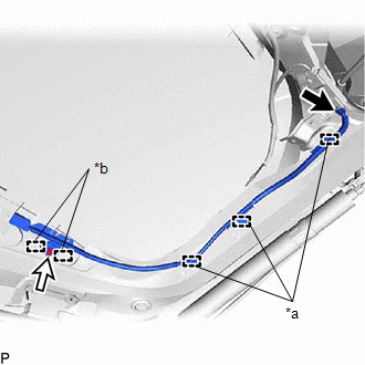
(b) Connect the connector.
| (c) Install the No. 4 antenna cord sub-assembly with the bolt. Torque: for Type A : 8.35 N·m {85 kgf·cm, 74 in·lbf} for Type B : 10 N·m {102 kgf·cm, 7 ft·lbf} NOTICE: There are two types of bolts and the tightening torque depends on the type of bolt used as shown in the illustration. Therefore, confirm the tightening torque before installing the bolt. |
|
.png)
2. INSTALL NO. 3 ANTENNA CORD SUB-ASSEMBLY
| (a) Engage the 2 grommets as shown in the illustration. |
|
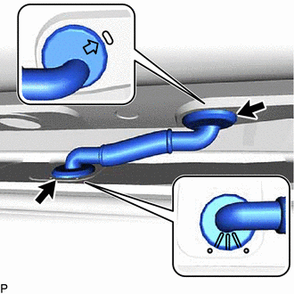
(b) Connect the washer hose.
| (c) Connect the 2 connectors and washer hose to install the No. 3 antenna cord sub-assembly. NOTICE: Route the No. 3 antenna cord sub-assembly around the right side of the connector as shown in the illustration. |
|
3. INSTALL BACK DOOR TRIM PANEL ASSEMBLY
Click here .gif)
4. INSTALL NO. 1 LUGGAGE COMPARTMENT LIGHT ASSEMBLY
Click here
5. INSTALL DOOR PULL HANDLE
Click here
6. INSTALL BACK DOOR TRIM BASE
Click here
7. INSTALL BACK DOOR LOCK COVER
Click here
8. INSTALL BACK DOOR TRIM COVER LH
Click here
9. INSTALL BACK DOOR TRIM COVER RH
HINT:
Use the same procedure as for the LH side.
10. INSTALL BACK WINDOW UPPER PANEL TRIM
Click here
11. INSTALL NO. 5 ANTENNA CORD SUB-ASSEMBLY (w/o Satellite Radio)
(a) Engage each clamp.
(b) Connect each connector to install the No. 5 antenna cord sub-assembly.
12. INSTALL NO. 6 ANTENNA CORD SUB-ASSEMBLY (w/ Satellite Radio)
(a) Engage each clamp.
(b) Connect each connector to install the No. 6 antenna cord sub-assembly.
13. INSTALL NO. 2 ANTENNA CORD SUB-ASSEMBLY
HINT:
Butyl tape and adhesive tape are not available as supply parts. If these pieces of tape still have enough adhesion to secure the No. 2 antenna cord sub-assembly to the roof headlining assembly, reuse them. If the adhesive tape and/or the butyl tape is no longer sticky, apply new tape following the procedure below.
(a) Apply new butyl tape.
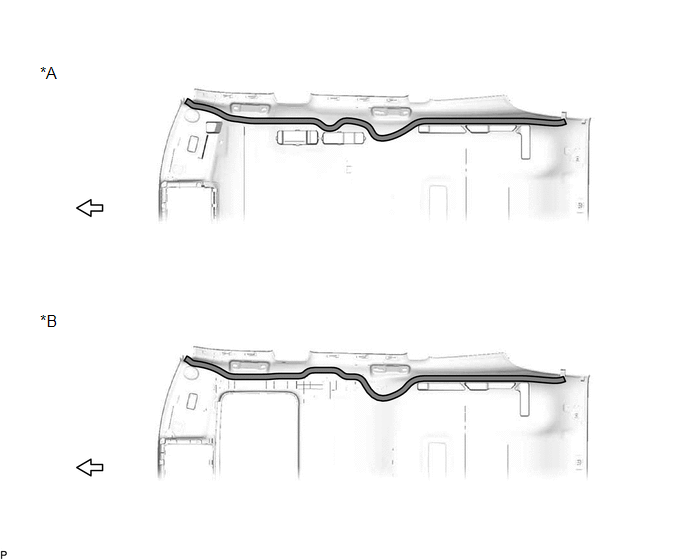
| *A | for Standard Roof | *B | for Sliding Roof |
 | Butyl tape | .png) | Front |
(1) Remove the old butyl tape from the roof headlining assembly.
(2) Prepare an appropriate amount of new butyl tape.
HINT:
Be careful not to touch the adhesive surface.
(3) Apply the butyl tape to the roof headlining assembly while aligning the tape with the markings on the roof headlining assembly.
(4) Peel off the release paper from the butyl tape.
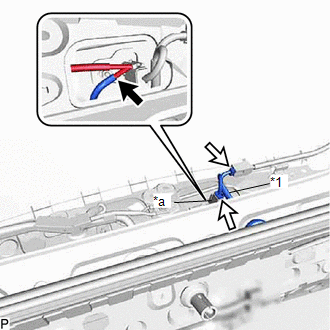
(b) Align the marking tape on the No. 2 antenna cord sub-assembly with the markings on the roof headlining assembly and install the No. 2 antenna cord sub-assembly to the butyl tape.
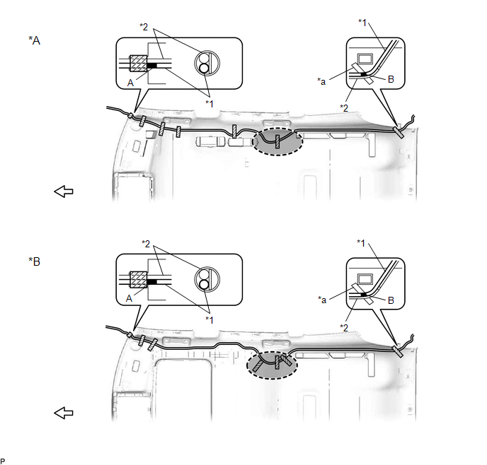
| *A | for Standard Roof | *B | for Sliding Roof |
| *1 | NO. 2 ANTENNA CORD SUB-ASSEMBLY | *2 | WASHER HOSE ASSEMBLY |
| *a | Marking | - | - |
.png) | Adhesive Tape |  | Marking Tape |
 | Adjustment Area | | Front |
(c) Put the pieces of adhesive tape back to the positions shown in the illustration to secure the No. 2 antenna cord sub-assembly and washer hose assembly to the roof headlining assembly.
HINT:
- If the tape is no longer sticky, use other tape, such as packing tape, that has enough adhesion to secure the antenna cord to the roof headlining assembly.
- Align the marking tape (A) on the No. 2 antenna cord sub-assembly with the base of the protrusion on the front right side of the roof headlining assembly and wrap tape around the No. 2 antenna cord sub-assembly, washer hose assembly and roof headlining assembly to secure them.
- Align the marking tape (B) on the No. 2 antenna cord sub-assembly with the marking on the rear of the roof headlining assembly and secure the No. 2 antenna cord sub-assembly and washer hose assembly with the No. 2 antenna cord sub-assembly on the outer side of the washer hose assembly.
- Secure the extra length of the No. 2 antenna cord sub-assembly in the adjustment area shown in the illustration.
14. INSTALL ROOF HEADLINING ASSEMBLY
Click here
15. INSTALL ANTENNA CORD SUB-ASSEMBLY
(a) Engage each clamp to install the antenna cord sub-assembly.
(b) Connect the connector.
(c) Engage the 2 claws.
16. INSTALL NO. 2 SIDE DEFROSTER NOZZLE DUCT
Click here
17. INSTALL NO. 4 HEATER TO REGISTER DUCT
Click here
18. INSTALL INSTRUMENT PANEL SAFETY PAD SUB-ASSEMBLY
Click here
 Removal
REMOVAL CAUTION / NOTICE / HINT The necessary procedures (adjustment, calibration, initialization, or registration) that must be performed after parts are removed and installed, or replaced during ant ...

Other materials:
Lexus RX (RX 350L, RX450h) 2016-2026 Repair Manual > Air Conditioning System: Parts Location
PARTS LOCATION ILLUSTRATION *A w/o Rear Air Conditioning System *B w/ PTC Heater *C w/ Smog Ventilation Sensor *D w/ Pre-collision System *1 AIR CONDITIONER PRESSURE SENSOR *2 COOLER (AMBIENT TEMP. SENSOR) THERMISTOR *3 COOLER COMPRESSOR ASSEMBLY *4 SEMICONDUC ...
Lexus RX (RX 350L, RX450h) 2016-2026 Repair Manual > Compressor: Components
COMPONENTS ILLUSTRATION *A for Type A *B for Type B *1 COMPRESSOR AND MAGNETIC CLUTCH *2 DISCHARGE HOSE SUB-ASSEMBLY *3 SUCTION HOSE SUB-ASSEMBLY *4 O-RING *5 BRACKET - - N*m (kgf*cm, ft.*lbf): Specified torque ● Non-reusable part Compresso ...
Lexus RX (RX 350L, RX450h) 2016-{YEAR} Owners Manual
- For your information
- Pictorial index
- For safety and security
- Instrument cluster
- Operation of each component
- Driving
- Lexus Display Audio system
- Interior features
- Maintenance and care
- When trouble arises
- Vehicle specifications
- For owners
Lexus RX (RX 350L, RX450h) 2016-{YEAR} Repair Manual

0.0138