Lexus RX (RX 350L, RX450h) 2016-2026 Repair Manual: Back Door Entry Lock Function does not Operate
DESCRIPTION
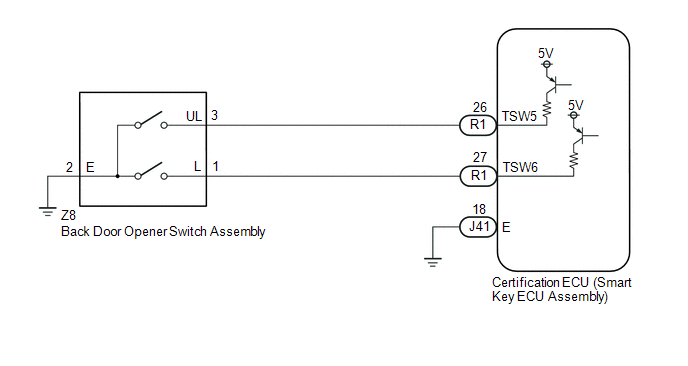
If the entry lock function does not operate for the back door only, but the entry unlock function operates, the request code is being transmitted properly from the back door. In this case, there may be a problem related to the lock switch (connection between the back door opener switch assembly and certification ECU (smart key ECU assembly)).
WIRING DIAGRAM
CAUTION / NOTICE / HINT
NOTICE:
-
The smart access system with push-button start (for Entry Function) uses the LIN communication system and CAN communication system. Inspect the communication function by following How to Proceed with Troubleshooting. Troubleshoot the smart access system with push-button start (for Entry Function) after confirming that the communication systems are functioning properly.
Click here
.gif)
- When using the Techstream with the engine switch off, connect the Techstream to the DLC3 and turn a courtesy light switch on and off at intervals of 1.5 seconds or less until communication between the Techstream and the vehicle begins. Then select the vehicle type under manual mode and enter the following menus: Body Electrical / Smart Access. While using the Techstream, periodically turn a courtesy light switch on and off at intervals of 1.5 seconds or less to maintain communication between the Techstream and the vehicle.
- Check that there are no electrical key transmitter sub-assemblies in the vehicle.
-
Before replacing the certification ECU (smart key ECU assembly), refer to Precaution.
Click here
- After repair, confirm that no DTCs are output.
PROCEDURE
| 1. | CHECK POWER DOOR LOCK CONTROL SYSTEM |
(a) When the door control switch on the multiplex network master switch assembly is operated, check that the doors unlock and lock according to the switch operation.
Click here
OK:
Door locks operate normally.
| NG | .gif) | GO TO POWER DOOR LOCK CONTROL SYSTEM |
|
.gif)
| 2. | INSPECT TECHSTREAM (TR/B-DOOR LOCK SW) |
(a) Connect the Techstream to the DLC3.
(b) Turn the engine switch on (IG).
(c) Turn the Techstream on.
(d) Enter the following menus: Body Electrical / Smart Access / Data List.
(e) Read the Data List according to the display on the Techstream.
Body Electrical > Smart Access > Data List| Tester Display | Measurement Item | Range | Normal Condition | Diagnostic Note |
|---|---|---|---|---|
| Tr/B-Door Lock SW | Back door opener switch assembly (lock switch) | ON or OFF | ON: Back door opener switch assembly (lock switch) pressed OFF: Back door opener switch assembly (lock switch) not pressed |
|
| Tester Display |
|---|
| Tr/B-Door Lock SW |
HINT:
When checking the operation of the entry lock function several times, it can be operated up to 2 times consecutively. To operate the function 3 times or more consecutively, the doors need to be unlocked once. However, this is only for the entry lock function, other door lock operations, such as a wireless door lock operation can be performed consecutively.
OK:
The Techstream display changes correctly in response to the operation of the back door opener switch assembly.
| OK | | REPLACE CERTIFICATION ECU (SMART KEY ECU ASSEMBLY) |
|
| 3. | CHECK HARNESS AND CONNECTOR (BACK DOOR OPENER SWITCH ASSEMBLY - CERTIFICATION ECU (SMART KEY ECU ASSEMBLY)) |
(a) Disconnect the R1 certification ECU (smart key ECU assembly) connector.
(b) Disconnect the Z8 back door opener switch assembly connector.
(c) Measure the resistance according to the value(s) in the table below.
Standard Resistance:
| Tester Connection | Condition | Specified Condition |
|---|---|---|
| R1-27 (TSW6) - Z8-1 (L) | Always | Below 1 Ω |
| Z8-2 (E) - Body ground | Always | Below 1 Ω |
| R1-27 (TSW6) or Z8-1 (L) - Body ground | Always | 10 kΩ or higher |
| NG | | REPAIR OR REPLACE HARNESS OR CONNECTOR |
|
| 4. | INSPECT BACK DOOR OPENER SWITCH ASSEMBLY (LOCK SWITCH) |
(a) Remove the back door opener switch assembly.
Click here
(b) Inspect the back door opener switch assembly.
Click here
| OK | | REPLACE CERTIFICATION ECU (SMART KEY ECU ASSEMBLY) |
| NG | | REPLACE BACK DOOR OPENER SWITCH ASSEMBLY |
 Back Door Entry Lock and Unlock Functions do not Operate
DESCRIPTION If the entry lock and unlock functions do not operate for the back door only, the request code may not be being transmitted from the back door. If the entry functions for other doors opera ...
 New Key cannot be Registered
DESCRIPTION If a new electrical key transmitter sub-assembly could not be registered, wave interference or a malfunction of the certification ECU (smart key ECU assembly), electrical key transmitter s ...
Other materials:
Lexus RX (RX 350L, RX450h) 2016-2026 Repair Manual > Rear Power Seat Control System(for Third Row): How To Proceed With Troubleshooting
PROCEDURE 1. VEHICLE BROUGHT TO WORKSHOP
NEXT 2. CUSTOMER PROBLEM ANALYSIS HINT:
In troubleshooting, confirm that the problem symptoms have been accurately identified. Preconceptions should be discarded in order to make an accurate judgment. To clearly understan ...
Lexus RX (RX 350L, RX450h) 2016-2026 Owners Manual > BSM (Blind Spot Monitor): RCTA function
The RCTA function uses radar sensors to detect vehicles approaching from the
right or left at the rear of the vehicle and alerts the driver of the presence
of such
vehicles by flashing the outside rear view mirror indicators and sounding a
buzzer.
Approaching vehicles
Detection areas of ...
Lexus RX (RX 350L, RX450h) 2016-{YEAR} Owners Manual
- For your information
- Pictorial index
- For safety and security
- Instrument cluster
- Operation of each component
- Driving
- Lexus Display Audio system
- Interior features
- Maintenance and care
- When trouble arises
- Vehicle specifications
- For owners
Lexus RX (RX 350L, RX450h) 2016-{YEAR} Repair Manual

0.0125