Lexus RX (RX 350L, RX450h) 2016-2026 Repair Manual: Lost Communication with Blind Spot Monitor Slave Module (U0232)
DESCRIPTION
This DTC is stored when the blind spot monitor sensor LH judges that there is a communication problem with the blind spot monitor sensor RH.
| DTC No. | Detection Item | DTC Detection Condition | Trouble Area |
|---|---|---|---|
| U0232 | Lost Communication with Blind Spot Monitor Slave Module | The blind spot monitor sensor (master) cannot receive signals from the blind spot monitor sensor (slave) |
|
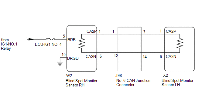
WIRING DIAGRAM
CAUTION / NOTICE / HINT
NOTICE:
- When checking for DTCs, make sure that the blind spot monitor system is turned on.
- Inspect the fuses for circuits related to this system before performing the following procedure.
- Before measuring the resistance of the CAN bus, turn the engine switch off and leave the vehicle for 1 minute or more without operating the key or any switches, or opening or closing the doors. After that, disconnect the cable from the negative (-) battery terminal and leave the vehicle for 1 minute or more before measuring the resistance.
-
After turning the engine switch off, waiting time may be required before disconnecting the cable from the negative (-) battery terminal. Therefore, make sure to read the disconnecting the cable from the negative (-) battery terminal notices before proceeding with work.
Click here
.gif)
HINT:
- Operating the engine switch, any other switches or a door triggers related ECU and sensor communication on the CAN. This communication will cause the resistance value to change.
- Even after DTCs are cleared, if a DTC is stored again after driving the vehicle for a while, the malfunction may be occurring due to vibration of the vehicle. In such a case, wiggling the ECUs or wire harness while performing the inspection below may help determine the cause of the malfunction.
PROCEDURE
| 1. | CONFIRM MODEL |
(a) Choose the model to be inspected.
| Result | Proceed to |
|---|---|
| w/ Intelligent Clearance Sonar System | A |
| w/o Intelligent Clearance Sonar System | B |
| B |  | GO TO STEP 3 |
|

| 2. | CHECK DTC OUTPUT (INTELLIGENT CLEARANCE SONAR SYSTEM) |
(a) Using the GTS, check for DTCs according to the prompts on the screen.
Click here
Standard:
The clearance warning ECU assembly does not output DTCs U0232 and U0233 simultaneously.
| NG | | GO TO INTELLIGENT CLEARANCE SONAR SYSTEM (DTC U0232) |
|
| 3. | CHECK CAN BUS MAIN WIRE |
(a) Turn the engine switch off.
(b) Disconnect the cable from the negative (-) battery terminal.
| (c) Measure the resistance according to the value(s) in the table below. Standard Resistance:
|
|
| Result | Proceed to |
|---|---|
| OK | A |
| Open circuit in CAN main bus lines | B |
| Short circuit between bus lines | C |
| D |
| B | | GO TO STEP 9 |
| C | | GO TO STEP 12 |
| D | | GO TO STEP 15 |
|
| 4. | CHECK HARNESS AND CONNECTOR (BLIND SPOT MONITOR SENSOR RH - BODY GROUND) |
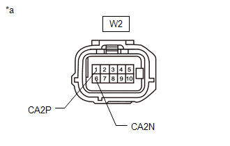
(a) Disconnect the W2 blind spot monitor sensor RH connector.
(b) Measure the resistance according to the value(s) in the table below.
Standard Resistance:
| Tester Connection | Condition | Specified Condition |
|---|---|---|
| W2-10 (BRGD) - Body ground | Always | Below 1 Ω |
| NG | | REPAIR OR REPLACE HARNESS OR CONNECTOR |
|
| 5. | CHECK HARNESS AND CONNECTOR (BLIND SPOT MONITOR SENSOR RH POWER SOURCE) |
(a) Disconnect the W2 blind spot monitor sensor RH connector.
(b) Measure the voltage according to the value(s) in the table below.
Standard Voltage:
| Tester Connection | Condition | Specified Condition |
|---|---|---|
| W2-5 (BRB) - Body ground | Engine switch on (IG) | 11 to 14 V |
| W2-5 (BRB) - Body ground | Engine switch off | Below 1 V |
| NG | | REPAIR OR REPLACE HARNESS OR CONNECTOR |
|
| 6. | CHECK DTC |
(a) Reconnect the cable to the negative (-) battery terminal.
(b) Turn the engine switch off.
(c) Turn the engine switch on (IG).
(d) Check for DTCs.
Click here
OK:
No DTCs are output.
| OK | | USE SIMULATION METHOD TO CHECK |
|
| 7. | REPLACE BLIND SPOT MONITOR SENSOR RH |
(a) Replace the blind spot monitor sensor RH.
Click here
|
| 8. | RECHECK DTC |
(a) Clear the DTCs.
Click here
(b) Recheck for DTCs and check if the same DTC is output again.
Body Electrical > Blind Spot Monitor Master > Trouble CodesOK:
No DTCs are output.
| OK | | END |
| NG | | REPLACE BLIND SPOT MONITOR SENSOR LH |
| 9. | CHECK FOR OPEN IN CAN BUS MAIN WIRE (NO. 6 CAN JUNCTION CONNECTOR) |
| (a) Disconnect the J98 No. 6 CAN junction connector. |
|
(b) Measure the resistance according to the value(s) in the table below.
Standard Resistance:
| Tester Connection | Condition | Specified Condition |
|---|---|---|
| J98-3 (CANH) - J98-14(CANL) | Cable disconnected from negative (-) battery terminal | 108 to 132 Ω |
| J98-1 (CANH) - J98-12(CANL) | Cable disconnected from negative (-) battery terminal | 108 to 132 Ω |
| Result | Proceed to |
|---|---|
| OK | A |
| NG (to blind spot monitor sensor LH CAN main wire) | B |
| NG (to blind spot monitor sensor RH CAN main wire) | C |
| A | | REPLACE NO. 6 CAN JUNCTION CONNECTOR |
| C | | GO TO STEP 11 |
|
| 10. | CHECK FOR OPEN IN CAN BUS MAIN WIRE (BLIND SPOT MONITOR SENSOR LH) |
(a) Reconnect the J98 No. 6 CAN junction connector.
| (b) Disconnect the X2 blind spot monitor sensor LH connector. |
|

(c) Measure the resistance according to the value(s) in the table below.
Standard Resistance:
| Tester Connection | Condition | Specified Condition |
|---|---|---|
| X2-1 (CA2P) - X2-6 (CA2N) | Cable disconnected from negative (-) battery terminal | 108 to 132 Ω |
| OK | | REPLACE BLIND SPOT MONITOR SENSOR LH |
| NG | | REPAIR OR REPLACE CAN MAIN WIRE OR CONNECTOR (BLIND SPOT MONITOR SENSOR LH - NO. 6 CAN JUNCTION CONNECTOR) |
| 11. | CHECK FOR OPEN IN CAN BUS MAIN WIRE (BLIND SPOT MONITOR SENSOR RH) |
(a) Reconnect the J98 No. 6 CAN junction connector.
| (b) Disconnect the W2 blind spot monitor sensor RH connector. |
|
(c) Measure the resistance according to the value(s) in the table below.
Standard Resistance:
| Tester Connection | Condition | Specified Condition |
|---|---|---|
| W2-1 (CA2P) -W2-6 (CA2N) | Cable disconnected from negative (-) battery terminal | 108 to 132 Ω |
| OK | | REPLACE BLIND SPOT MONITOR SENSOR RH |
| NG | | REPAIR OR REPLACE CAN MAIN WIRE OR CONNECTOR (BLIND SPOT MONITOR SENSOR RH - NO. 6 CAN JUNCTION CONNECTOR) |
| 12. | CHECK FOR SHORT IN CAN BUS WIRES (NO. 6 CAN JUNCTION CONNECTOR) |
| (a) Disconnect the J98 No. 6 CAN junction connector. |
|
(b) Measure the resistance according to the value(s) in the table below.
Standard Resistance:
| Tester Connection | Condition | Specified Condition |
|---|---|---|
| J98-3 (CANH) - J98-14(CANL) | Cable disconnected from negative (-) battery terminal | 108 to 132 Ω |
| J98-1 (CANH) - J98-12(CANL) | Cable disconnected from negative (-) battery terminal | 108 to 132 Ω |
| Result | Proceed to |
|---|---|
| OK | A |
| NG (to blind spot monitor sensor LH CAN main wire) | B |
| NG (to blind spot monitor sensor RH CAN main wire) | C |
| A | | REPLACE NO. 6 CAN JUNCTION CONNECTOR |
| C | | GO TO STEP 14 |
|
| 13. | CHECK FOR SHORT IN CAN BUS WIRES (BLIND SPOT MONITOR SENSOR LH) |
(a) Reconnect the J98 No. 6 CAN junction connector.
| (b) Disconnect the X2 blind spot monitor sensor LH connector. |
|
(c) Measure the resistance according to the value(s) in the table below.
Standard Resistance:
| Tester Connection | Condition | Specified Condition |
|---|---|---|
| X2-1 (CA2P) - X2-6 (CA2N) | Cable disconnected from negative (-) battery terminal | 108 to 132 Ω |
| OK | | REPLACE BLIND SPOT MONITOR SENSOR LH |
| NG | | REPAIR OR REPLACE CAN MAIN WIRE OR CONNECTOR (BLIND SPOT MONITOR SENSOR LH - NO. 6 CAN JUNCTION CONNECTOR) |
| 14. | CHECK FOR SHORT IN CAN BUS WIRES (BLIND SPOT MONITOR SENSOR RH) |
(a) Reconnect the J98 No. 6 CAN junction connector.
| (b) Disconnect the W2 blind spot monitor sensor RH connector. |
|
(c) Measure the resistance according to the value(s) in the table below.
Standard Resistance:
| Tester Connection | Condition | Specified Condition |
|---|---|---|
| W2-1 (CA2P) -W2-6 (CA2N) | Cable disconnected from negative (-) battery terminal | 108 to 132 Ω |
| OK | | REPLACE BLIND SPOT MONITOR SENSOR RH |
| NG | | REPAIR OR REPLACE CAN MAIN WIRE OR CONNECTOR (BLIND SPOT MONITOR SENSOR RH - NO. 6 CAN JUNCTION CONNECTOR) |
| 15. | CHECK FOR SHORT IN CAN BUS WIRES (NO. 6 CAN JUNCTION CONNECTOR) |
(a) Disconnect the J98 No. 6 CAN junction connector.
(b) Measure the resistance according to the value(s) in the table below.
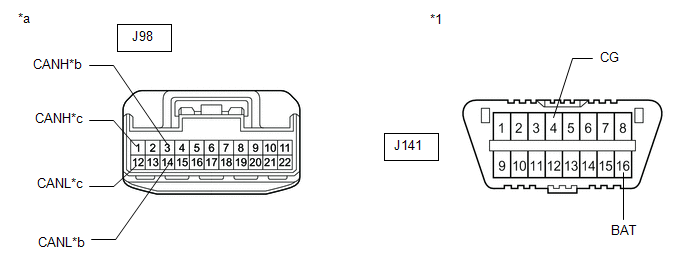
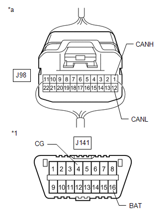
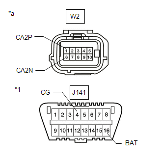
| *1 | DLC3 | - | - |
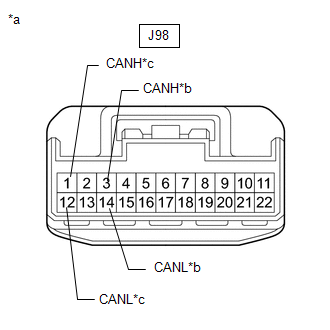
| *a | Front view of wire harness connector (to No. 6 CAN Junction Connector) | *b | to blind spot monitor sensor LH CAN main wire |
| *c | to blind spot monitor sensor RH CAN main wire | - | - |
Standard Resistance:
| Tester Connection | Condition | Specified Condition |
|---|---|---|
| J98-3 (CANH) - J141-4 (CG) | Cable disconnected from negative (-) battery terminal | 200 Ω or higher |
| J98-14 (CANL) - J141-4 (CG) | Cable disconnected from negative (-) battery terminal | 200 Ω or higher |
| J98-3 (CANH) - J141-16 (BAT) | Cable disconnected from negative (-) battery terminal | 6 kΩ or higher |
| J98-14 (CANL) - J141-16 (BAT) | Cable disconnected from negative (-) battery terminal | 6 kΩ or higher |
| J98-1 (CANH) - J141-4 (CG) | Cable disconnected from negative (-) battery terminal | 200 Ω or higher |
| J98-12 (CANL) - J141-4 (CG) | Cable disconnected from negative (-) battery terminal | 200 Ω or higher |
| J98-1 (CANH) - J141-16 (BAT) | Cable disconnected from negative (-) battery terminal | 6 kΩ or higher |
| J98-12 (CANL) - J141-16 (BAT) | Cable disconnected from negative (-) battery terminal | 6 kΩ or higher |
| Result | Proceed to |
|---|---|
| OK | A |
| NG (to blind spot monitor sensor LH CAN main wire) | B |
| NG (to blind spot monitor sensor RH CAN main wire) | C |
| A | | REPLACE NO. 6 CAN JUNCTION CONNECTOR |
| C | | GO TO STEP 17 |
|
| 16. | CHECK FOR SHORT IN CAN BUS WIRES (BLIND SPOT MONITOR SENSOR LH) |
(a) Reconnect the J98 No. 6 CAN junction connector.
(b) Disconnect the X2 blind spot monitor sensor LH connector.
| (c) Measure the resistance according to the value(s) in the table below. Standard Resistance:
|
|

| OK | | REPLACE BLIND SPOT MONITOR SENSOR LH |
| NG | | REPAIR OR REPLACE CAN MAIN WIRE OR CONNECTOR (BLIND SPOT MONITOR SENSOR LH - NO. 6 CAN JUNCTION CONNECTOR) |
| 17. | CHECK FOR SHORT IN CAN BUS WIRES (BLIND SPOT MONITOR SENSOR RH) |
(a) Reconnect the J98 No. 6 CAN junction connector.
(b) Disconnect the W2 blind spot monitor sensor RH connector.
| (c) Measure the resistance according to the value(s) in the table below. Standard Resistance:
|
|
| OK | | REPLACE BLIND SPOT MONITOR SENSOR RH |
| NG | | REPAIR OR REPLACE CAN MAIN WIRE OR CONNECTOR (BLIND SPOT MONITOR SENSOR RH - NO. 6 CAN JUNCTION CONNECTOR) |
 Lost Communication with ECM / PCM "A" (U0100,U0125,U0126,U0129,U0142)
DESCRIPTION These DTCs are stored if there is a malfunction in the CAN communication system connected to the blind spot monitor sensor. HINT: If CAN communication system DTCs are stored, they may also ...
 Software Incompatibility with Body Control Module "B" (U1331)
DESCRIPTION This DTC is stored when the destination information of the main body ECU (multiplex network body ECU) does not match that of the blind spot monitor sensors. DTC No. Detection Item D ...
Other materials:
Lexus RX (RX 350L, RX450h) 2016-2026 Repair Manual > Automatic Transaxle System: Mechanical System Tests
MECHANICAL SYSTEM TESTS STALL SPEED TEST HINT: This test is to check the overall performance of the engine and transaxle. CAUTION:
This test should be done on a paved surface (a surface that is not slippery).
To ensure safety, perform this test in an open and level area that provides good tract ...
Lexus RX (RX 350L, RX450h) 2016-2026 Repair Manual > Rear Drive Shaft Assembly: Installation
INSTALLATION CAUTION / NOTICE / HINT HINT:
Use the same procedure for the RH side and LH side.
The following procedure is for the LH side.
PROCEDURE 1. INSTALL REAR DRIVE SHAFT SNAP RING (a) Install a new rear drive shaft snap ring. NOTICE: Face the end gap of the rear drive shaft snap ring ...
Lexus RX (RX 350L, RX450h) 2016-{YEAR} Owners Manual
- For your information
- Pictorial index
- For safety and security
- Instrument cluster
- Operation of each component
- Driving
- Lexus Display Audio system
- Interior features
- Maintenance and care
- When trouble arises
- Vehicle specifications
- For owners
Lexus RX (RX 350L, RX450h) 2016-{YEAR} Repair Manual

0.0089