Lexus RX (RX 350L, RX450h) 2016-2026 Repair Manual: Terminals Of Ecu
TERMINALS OF ECU
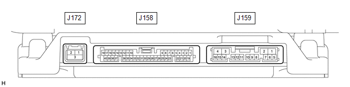
PARKING ASSIST ECU
(a) Disconnect the J159 parking assist ECU connector.
(b) Measure the voltage and resistance according to the value(s) in the table below.
| Terminal No. (Symbol) | Wiring Color | Terminal Description | Condition | Specified Condition |
|---|---|---|---|---|
| J159-1 (+B) - J159-4 (GND1) | LA-L - LA | Power source signal | Always | 11 to 14 V |
| J159-2 (ACC) - J159-4 (GND1) | V - LA | ACC power source signal | Engine switch on (ACC) | 11 to 14 V |
| Engine switch off | Below 1 V | |||
| J159-3 (IG) - J159-4 (GND1) | P - LA | IG power source signal | Engine switch on (IG) | 11 to 14 V |
| Engine switch off | Below 1 V | |||
| J159-4 (GND1) - Body ground | LA - Body ground | Ground | Always | Below 1 Ω |
(c) Connect the J159 parking assist ECU connector.
(d) Measure the voltage, resistance and waveform according to the value(s) in the table below.
| Terminal No. (Symbol) | Wiring Color | Terminal Description | Condition | Specified Condition |
|---|---|---|---|---|
| J158-6 (RSW+) - J159-4 (GND1) | B - LA | Terminal required by law | Panoramic image being displayed | 0 to 2 V |
| Panoramic image not being displayed | 5.5 to 7.05 V | |||
| J158-10 (LCV+) - J158-35 (LGND) | BR - SB | Side television camera assembly LH display signal input | Engine switch on (IG), panoramic view monitor switch on, camera lens not covered, displaying image | Pulse generation (See waveform 1) |
| Engine switch on (IG), panoramic view monitor switch on, camera lens covered, blacking out screen | Pulse generation (See waveform 2) | |||
| J158-11 (SGND) - J158-35 (LGND) | B - SB | Side television camera assembly LH ground (shield) | Always | Below 1 Ω |
| J158-12 (LCB+) - J158-35 (LGND) | P - SB | Power source to side television camera assembly LH | Engine switch on (IG) | 5.5 to 7.05 V |
| J158-13 (BCV-) - J159-4 (GND1) | R - LA | Front television camera assembly ground | Always | Below 1 Ω |
| J158-14 (SGND) - J158-37 (BGND) | V - W | Front television camera assembly ground (shield) | Always | Below 1 Ω |
| J158-15 (BCB+) - J158-37 (BGND) | G - W | Power source to front television camera assembly | Engine switch on (IG) | 5.5 to 7.05 V |
| J158-16 (RCV-) - J159-4 (GND1) | R - LA | Side television camera assembly RH ground | Always | Below 1 Ω |
| J158-17 (RGND) - Body ground | G - Body ground | Side television camera assembly RH ground | Always | Below 1 Ω |
| J158-29 (CV+) - J158-32 (CGND) | B - G | Rear television camera assembly display signal input | Engine switch on (IG), panoramic view monitor switch on, camera lens not covered, displaying image | Pulse generation (See waveform 1) |
| Engine switch on (IG), panoramic view monitor switch on, camera lens covered, blacking out screen | Pulse generation (See waveform 2) | |||
| J158-30 (CV-) - J159-4 (GND1) | R - LA | Rear television camera assembly ground | Always | Below 1 V |
| J158-31 (SGND) - J158-32 (CGND) | V - G | Rear television camera assembly ground (shield) | Always | Below 1 Ω |
| J158-32 (CGND) - Body ground | G - Body ground | Rear television camera assembly ground | Always | Below 1 Ω |
| J158-33 (CB+) - J158-32 (CGND) | B - G | Power source to rear television camera assembly | Engine switch on (IG) | 5.5 to 7.05 V |
| J158-34 (LCV-) - J159-4 (GND1) | LG - LA | Side television camera assembly LH ground | Always | Below 1 Ω |
| J158-35 (LGND) - Body ground | SB - Body ground | Side television camera assembly LH ground | Always | Below 1 Ω |
| J158-36 (BCV+) - J158-37 (BGND) | B - W | Front television camera assembly display signal input | Engine switch on (IG), panoramic view monitor switch on, camera lens not covered, displaying image | Pulse generation (See waveform 1) |
| Engine switch on (IG), panoramic view monitor switch on, camera lens covered, blacking out screen | Pulse generation (See waveform 2) | |||
| J158-37 (BGND) - Body ground | W - Body ground | Front television camera assembly ground | Always | Below 1 Ω |
| J158-38 (RCV+) - J158-17 (RGND) | W - G | Side television camera assembly RH display signal input | Engine switch on (IG), panoramic view monitor switch on, camera lens not covered, displaying image | Pulse generation (See waveform 1) |
| Engine switch on (IG), panoramic view monitor switch on, camera lens covered, blacking out screen | Pulse generation (See waveform 2) | |||
| J158-39 (SGND) - J158-17 (RGND) | Shielded - G | Side television camera assembly RH ground (shield) | Always | Below 1 Ω |
| J158-40 (RCB+) - J158-17 (RGND) | B - G | Power source to side television camera assembly RH | Engine switch on (IG) | 5.5 to 7.05 V |
| J159-9 (CA2H) | R | CAN communication line | - | - |
| J159-10 (CA2L) | W | CAN communication line | - | - |
| J159-11 (CANH) | LG | CAN communication line | - | - |
| J159-12 (CANL) | W | CAN communication line | - | - |
| J159-14 (REV) - J159-4 (GND1) | LG - LA | Reverse signal | Engine switch on (IG), shift lever in R | 11 to 14 V |
| Engine switch on (IG), shift lever in other than R | Below 1 V | |||
| J159-15 (BLSW) - J159-4 (GND1) | V - LA | Panoramic view monitor switch signal | Engine switch on (IG), panoramic view monitor switch off | 5.5 to 6.5 V |
| Engine switch on (IG), panoramic view monitor switch on | Below 1 V | |||
| J172-1 (GVO+) | - | Video signal (Digital) | - | - |
| J172-2 (GVO-) | - | Video signal (Digital) | - | - |
| J172-3 (GVG1) | Shielded | Shield ground | - | - |
(e) Reference (Oscilloscope waveform):
HINT:
A waterproof connector is used for the rear television camera assembly, front television camera assembly, side television camera assembly LH and side television camera assembly RH. Therefore, inspect the waveform at the parking assist ECU with the connector connected.
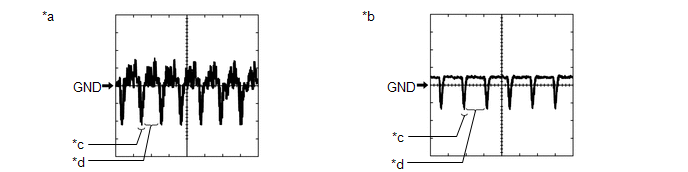
| *a | Waveform 1 | *b | Waveform 2 |
| *c | Synchronization Signal | *d | Video Waveform |
| Item | Content |
|---|---|
| Measurement terminal |
|
| Measurement setting | 200 mV/DIV., 50 μs./DIV. |
| Condition |
|
HINT:
- The video waveform changes according to the image sent by the rear television camera assembly, front television camera assembly, side television camera assembly LH or side television camera assembly RH.
- The video waveform is constantly output when the engine switch is on (ACC).
RADIO RECEIVER ASSEMBLY
w/ Audio and Visual System (for 12.3 Inch Display): Click here .gif)
w/ Audio and Visual System (for 8 Inch Display): Click here
w/ Navigation System: Click here
 Problem Symptoms Table
PROBLEM SYMPTOMS TABLE NOTICE:
The following inspection procedure of the panoramic view monitor system is described on the assumption that the navigation system*1 or audio and visual system*2 is no ...
 Calibration
CALIBRATION ADJUST PANORAMIC VIEW MONITOR SYSTEM (a) This panoramic view monitor system can be set from the diagnostic screen of the multi-display assembly. (b) If the following operations are perform ...
Other materials:
Lexus RX (RX 350L, RX450h) 2016-2026 Repair Manual > Front Camera System: How To Proceed With Troubleshooting
CAUTION / NOTICE / HINT HINT:
Before performing troubleshooting for the front camera system, perform troubleshooting for the pre-collision system.
Click here
If a pre-collision system related warning message is displayed on the multi-information display, refer to How to Proceed with Troublesh ...
Lexus RX (RX 350L, RX450h) 2016-2026 Repair Manual > Water Pump: Installation
INSTALLATION PROCEDURE 1. INSTALL ENGINE WATER PUMP ASSEMBLY (a) Install a new water pump gasket and engine water pump assembly together with the water pump pulley with the 15 bolts. Torque: Bolt (A) : 43 N·m {438 kgf·cm, 32 ft·lbf} Bolt (B) : 21 N·m {214 kgf·cm, 15 ft·lbf} Bolt (C) and ...
Lexus RX (RX 350L, RX450h) 2016-{YEAR} Owners Manual
- For your information
- Pictorial index
- For safety and security
- Instrument cluster
- Operation of each component
- Driving
- Lexus Display Audio system
- Interior features
- Maintenance and care
- When trouble arises
- Vehicle specifications
- For owners
Lexus RX (RX 350L, RX450h) 2016-{YEAR} Repair Manual

0.0123