Lexus RX (RX 350L, RX450h) 2016-2026 Repair Manual: Front Camera Feedback Malfunction (C1681)
DESCRIPTION
DTC C1681 is stored if the parking assist ECU judges as a result of its self check that a synchronization problem is occurring in the image signal sent from the front television camera assembly to the parking assist ECU.
| DTC No. | Detection Item | DTC Detection Condition | Trouble Area |
|---|---|---|---|
| C1681 | Front Camera Feedback Malfunction | Front television camera power supply failure |
|
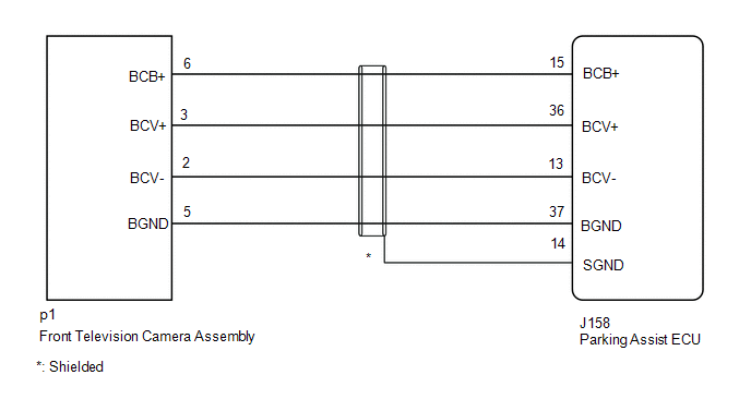
WIRING DIAGRAM
CAUTION / NOTICE / HINT
NOTICE:
-
When "!" is displayed on the multi-display assembly after the cable is disconnected from the negative (-) battery terminal, correct the steering angle neutral point.
Click here
.gif)
-
Depending on the parts that are replaced or operations that are performed during vehicle inspection or maintenance, calibration of other systems as well as panoramic view monitor system may be needed.
Click here
PROCEDURE
| 1. | CHECK HARNESS AND CONNECTOR (PARKING ASSIST ECU - FRONT TELEVISION CAMERA ASSEMBLY) |
(a) Disconnect the J158 parking assist ECU connector.
(b) Disconnect the p1 front television camera assembly connector.
(c) Measure the resistance according to the value(s) in the table below.
Standard Resistance:
| Tester Connection | Condition | Specified Condition |
|---|---|---|
| J158-15 (BCB+) - p1-6 (BCB+) | Always | Below 1 Ω |
| J158-36 (BCV+) - p1-3 (BCV+) | Always | Below 1 Ω |
| J158-13 (BCV-) - p1-2 (BCV-) | Always | Below 1 Ω |
| J158-37 (BGND) - p1-5 (BGND) | Always | Below 1 Ω |
| J158-14 (SGND) - Body ground | Always | Below 1 Ω |
| J158-15 (BCB+) or p1-6 (BCB+) - Body ground | Always | 10 kΩ or higher |
| J158-36 (BCV+) or p1-3 (BCV+) - Body ground | Always | 10 kΩ or higher |
| J158-13 (BCV-) or p1-2 (BCV-) - Body ground | Always | 10 kΩ or higher |
| J158-37 (BGND) or p1-5 (BGND) - Body ground | Always | 10 kΩ or higher |
| NG | .gif) | REPAIR OR REPLACE HARNESS OR CONNECTOR |
|
.gif)
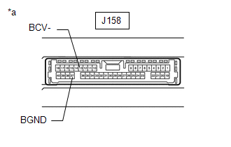
| 2. | CHECK PARKING ASSIST ECU (BCV-, BGND) |
| (a) Measure the resistance according to the value(s) in the table below. Standard Resistance:
|
|
| NG | | REPLACE PARKING ASSIST ECU |
|
| 3. | CHECK PARKING ASSIST ECU (BCB+, BGND) |
| (a) Connect the J158 parking assist ECU connector. |
|
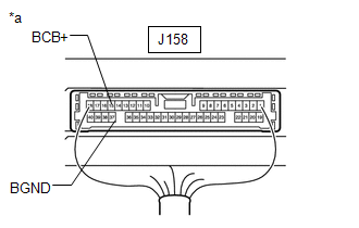
(b) Measure the voltage according to the value(s) in the table below.
Standard Voltage:
| Tester Connection | Switch Condition | Specified Condition |
|---|---|---|
| J158-15 (BCB+) - J158-37 (BGND) | Engine switch on (IG) | 5.5 to 7.05 V |
| NG | | REPLACE PARKING ASSIST ECU |
|
| 4. | CHECK FRONT TELEVISION CAMERA ASSEMBLY (BCV+, BGND) |
(a) Connect the p1 front television camera assembly connector.
(b) Using an oscilloscope, check the waveform of the front television camera assembly.
HINT:
A waterproof connector is used for the front television camera assembly. Therefore, inspect the waveform at the parking assist ECU with the connector connected.
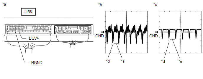
| *a | Component with harness connected (Parking Assist ECU) | *b | Waveform 1 |
| *c | Waveform 2 | *d | Synchronization Signal |
| *e | Video Waveform | - | - |
| Item | Content |
|---|---|
| Terminal No. (Symbol) | J158-36 (BCV+) - J158-37 (BGND) |
| Tool Setting | 200 mV/DIV., 50 μs./DIV. |
| Condition |
|
HINT:
- The video waveform changes according to the image sent by the front television camera assembly.
- The video waveform is constantly output when the engine switch is on (ACC).
OK:
Waveform is similar to that shown in the illustration.
| OK | | REPLACE PARKING ASSIST ECU |
| NG | | REPLACE FRONT TELEVISION CAMERA ASSEMBLY |
 Front Wheel Speed Sensor Malfunction (C164D)
DESCRIPTION This DTC is stored when the parking assist ECU receives a wheel speed sensor (front speed sensor RH or front speed sensor LH, rear speed sensor RH or rear speed sensor LH) abnormality sign ...
 Front Camera Current Malfunction (C1682)
DESCRIPTION DTC C1682 is stored if the parking assist ECU judges as a result of its self check that there is a problem with the current supplied from the front television camera assembly connected to ...
Other materials:
Lexus RX (RX 350L, RX450h) 2016-2026 Repair Manual > Luggage Speaker (w/o Rear No. 2 Seat): Inspection
INSPECTION PROCEDURE 1. INSPECT REAR NO. 3 SPEAKER ASSEMBLY (a) With the speaker installed, check that there is no looseness or other abnormalities. (b) Check that there is no foreign matter in the speaker, no tears on the speaker cone or other abnormalities. (c) Measure the resistance of the spe ...
Lexus RX (RX 350L, RX450h) 2016-2026 Repair Manual > Rear Seat Assembly (for 60/40 Split Seat Type Rh Side): Inspection
INSPECTION PROCEDURE 1. PRECAUTION NOTICE: After performing the following check, initialize the fold seat control ECU (initial position reset and initial position memorization). Click here 2. INSPECT REAR SEATBACK FRAME SUB-ASSEMBLY RH (a) Check the operation of the reclining motor. (1) Apply batt ...
Lexus RX (RX 350L, RX450h) 2016-{YEAR} Owners Manual
- For your information
- Pictorial index
- For safety and security
- Instrument cluster
- Operation of each component
- Driving
- Lexus Display Audio system
- Interior features
- Maintenance and care
- When trouble arises
- Vehicle specifications
- For owners
Lexus RX (RX 350L, RX450h) 2016-{YEAR} Repair Manual

0.0101