Lexus RX (RX 350L, RX450h) 2016-2026 Repair Manual: Left Rear Wheel Speed Sensor Circuit Short to Battery (C050C12)
DESCRIPTION
Refer to DTC C050C1F.
Click here .gif)
| DTC No. | Detection Item | DTC Detection Condition | Trouble Area |
|---|---|---|---|
| C050C12 | Left Rear Wheel Speed Sensor Circuit Short to Battery | The speed sensor short signal is ON continuously for 0.5 seconds or more. |
|
- *1: for AWD
- *2: for 2WD
- *3: w/ AVS
WIRING DIAGRAM
Click here
CAUTION / NOTICE / HINT
NOTICE:
-
After replacing the skid control ECU (brake actuator assembly), perform "Calibration".
Click here
-
After replacing or removing and installing a speed sensor, perform Dealer Mode (Signal Check) inspection to confirm that the speed sensors are operating correctly.
Click here
PROCEDURE
| 1. | CHECK VEHICLE SPECIFICATION |
(a) Check the vehicle specification.
| Result | Proceed to |
|---|---|
| w/o AVS (for AWD) | A |
| w/o AVS (for 2WD) | B |
| w/ AVS (for AWD) | C |
| w/ AVS (for 2WD) | D |
| B | .gif) | GO TO STEP 5 |
| C | | GO TO STEP 9 |
| D | | GO TO STEP 13 |
|
.gif)
| 2. | CHECK HARNESS AND CONNECTOR (SENSOR GROUND CIRCUIT) |
| (a) Make sure that there is no looseness at the locking part and the connecting part of the connectors. OK: The connector is securely connected. |
|
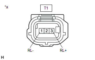
(b) Disconnect the T1 rear speed sensor LH connector.
(c) Check both the connector case and the terminals for deformation and corrosion.
OK:
No deformation or corrosion.
(d) Turn the engine switch on (IG).
(e) Measure the voltage according to the value(s) in the table below.
Standard Voltage:
| Tester Connection | Condition | Specified Condition |
|---|---|---|
| T1-3 (RL+) - T1-1 (RL-) | Engine switch on (IG) | 11 to 14 V |
| OK | | REPLACE REAR SPEED SENSOR LH |
|
| 3. | CHECK HARNESS AND CONNECTOR (SENSOR GROUND CIRCUIT) |
| (a) Turn the engine switch off. |
|
(b) Make sure that there is no looseness at the locking part and the connecting part of the connectors.
OK:
The connector is securely connected.
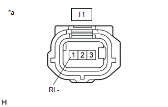
(c) Disconnect the A41 skid control ECU (brake actuator assembly) connector.
(d) Check both the connector case and the terminals for deformation and corrosion.
OK:
No deformation or corrosion.
(e) Measure the voltage according to the value(s) in the table below.
Standard Voltage:
| Tester Connection | Condition | Specified Condition |
|---|---|---|
| T1-1 (RL-) - Body ground | Always | Below 1.5 V |
| NG | | REPAIR OR REPLACE HARNESS OR CONNECTOR |
|
| 4. | CHECK HARNESS AND CONNECTOR (REAR SPEED SENSOR LH - BRAKE ACTUATOR ASSEMBLY) |
(a) Measure the resistance according to the value(s) in the table below.
Standard Resistance:
| Tester Connection | Condition | Specified Condition |
|---|---|---|
| T1-3 (RL+) or A41-5 (RL+) - T1-1 (RL-) or A41-4 (RL-) | Always | 10 kΩ or higher |
| OK | | REPLACE BRAKE ACTUATOR ASSEMBLY |
| NG | | REPAIR OR REPLACE HARNESS OR CONNECTOR |
| 5. | CHECK HARNESS AND CONNECTOR (SENSOR GROUND CIRCUIT) |
| (a) Make sure that there is no looseness at the locking part and the connecting part of the connectors. OK: The connector is securely connected. |
|
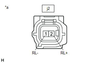
(b) Disconnect the j2 rear speed sensor LH (rear axle hub and bearing assembly LH) connector.
(c) Check both the connector case and the terminals for deformation and corrosion.
OK:
No deformation or corrosion.
(d) Turn the engine switch on (IG).
(e) Measure the voltage according to the value(s) in the table below.
Standard Voltage:
| Tester Connection | Condition | Specified Condition |
|---|---|---|
| j2-2 (RL+) - j2-1 (RL-) | Engine switch on (IG) | 11 to 14 V |
HINT:
The rear speed sensor LH is incorporated into the rear axle hub and bearing assembly LH.
If the rear speed sensor LH needs to be replaced, replace the rear axle hub and bearing assembly LH.
| OK | | REPLACE REAR AXLE HUB AND BEARING ASSEMBLY LH |
|
| 6. | CHECK HARNESS AND CONNECTOR (SENSOR GROUND CIRCUIT) |
| (a) Turn the engine switch off. |
|
(b) Make sure that there is no looseness at the locking part and the connecting part of the connectors.
OK:
The connector is securely connected.
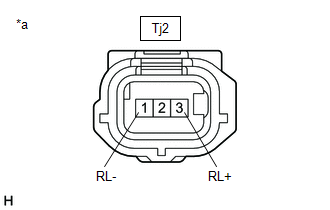
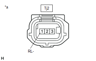
(c) Disconnect the Tj2 rear skid control sensor wire LH No. 1 connector.
(d) Check both the connector case and the terminals for deformation and corrosion.
OK:
No deformation or corrosion.
(e) Turn the engine switch on (IG).
(f) Measure the voltage according to the value(s) in the table below.
Standard Voltage:
| Tester Connection | Condition | Specified Condition |
|---|---|---|
| Tj2-3 (RL+) - Tj2-1 (RL-) | Engine switch on (IG) | 11 to 14 V |
| OK | | REPLACE REAR SKID CONTROL SENSOR WIRE LH NO. 1 |
|
| 7. | CHECK HARNESS AND CONNECTOR (SENSOR GROUND CIRCUIT) |
| (a) Turn the engine switch off. |
|
(b) Make sure that there is no looseness at the locking part and the connecting part of the connectors.
OK:
The connector is securely connected.
(c) Disconnect the A41 skid control ECU (brake actuator assembly) connector.
(d) Check both the connector case and the terminals for deformation and corrosion.
OK:
No deformation or corrosion.
(e) Measure the voltage according to the value(s) in the table below.
Standard Voltage:
| Tester Connection | Condition | Specified Condition |
|---|---|---|
| Tj2-1 (RL-) - Body ground | Always | Below 1.5 V |
| NG | | REPAIR OR REPLACE HARNESS OR CONNECTOR |
|
| 8. | CHECK HARNESS AND CONNECTOR (REAR SKID CONTROL SENSOR WIRE LH NO. 1 - BRAKE ACTUATOR ASSEMBLY) |
(a) Measure the resistance according to the value(s) in the table below.
Standard Resistance:
| Tester Connection | Condition | Specified Condition |
|---|---|---|
| Tj2-3 (RL+) or A41-5 (RL+) - Tj2-1 (RL-) or A41-4 (RL-) | Always | 10 kΩ or higher |
| OK | | REPLACE BRAKE ACTUATOR ASSEMBLY |
| NG | | REPAIR OR REPLACE HARNESS OR CONNECTOR |
| 9. | CHECK HARNESS AND CONNECTOR (SENSOR GROUND CIRCUIT) |
| (a) Make sure that there is no looseness at the locking part and the connecting part of the connectors. OK: The connector is securely connected. |
|
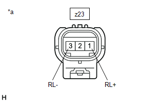
(b) Disconnect the z23 rear speed sensor LH connector.
(c) Check both the connector case and the terminals for deformation and corrosion.
OK:
No deformation or corrosion.
(d) Turn the engine switch on (IG).
(e) Measure the voltage according to the value(s) in the table below.
Standard Voltage:
| Tester Connection | Condition | Specified Condition |
|---|---|---|
| z23-1 (RL+) - z23-3 (RL-) | Engine switch on (IG) | 11 to 14 V |
| OK | | REPLACE REAR SPEED SENSOR LH |
|
| 10. | CHECK HARNESS AND CONNECTOR (SENSOR GROUND CIRCUIT) |
| (a) Turn the engine switch off. |
|
(b) Make sure that there is no looseness at the locking part and the connecting part of the connectors.
OK:
The connector is securely connected.
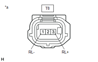
(c) Disconnect the T8 rear skid control sensor wire LH NO. 2 connector.
(d) Check both the connector case and the terminals for deformation and corrosion.
OK:
No deformation or corrosion.
(e) Turn the engine switch on (IG).
(f) Measure the voltage according to the value(s) in the table below.
Standard Voltage:
| Tester Connection | Condition | Specified Condition |
|---|---|---|
| T8-3 (RL+) - T8-1 (RL-) | Engine switch on (IG) | 11 to 14 V |
| OK | | REPLACE REAR SKID CONTROL SENSOR WIRE LH NO. 2 |
|
| 11. | CHECK HARNESS AND CONNECTOR (SENSOR GROUND CIRCUIT) |
| (a) Turn the engine switch off. |
|
(b) Make sure that there is no looseness at the locking part and the connecting part of the connectors.
OK:
The connector is securely connected.
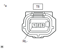
(c) Disconnect the A41 skid control ECU (brake actuator assembly) connector.
(d) Check both the connector case and the terminals for deformation and corrosion.
OK:
No deformation or corrosion.
(e) Measure the voltage according to the value(s) in the table below.
Standard Voltage:
| Tester Connection | Condition | Specified Condition |
|---|---|---|
| T8-1 (RL-) - Body ground | Always | Below 1.5 V |
| NG | | REPAIR OR REPLACE HARNESS OR CONNECTOR |
|
| 12. | CHECK HARNESS AND CONNECTOR (REAR SKID CONTROL SENSOR WIRE LH NO. 2 - BRAKE ACTUATOR ASSEMBLY) |
(a) Measure the resistance according to the value(s) in the table below.
Standard Resistance:
| Tester Connection | Condition | Specified Condition |
|---|---|---|
| T8-3 (RL+) or A41-5 (RL+) - T8-1 (RL-) or A41-4 (RL-) | Always | 10 kΩ or higher |
| OK | | REPLACE BRAKE ACTUATOR ASSEMBLY |
| NG | | REPAIR OR REPLACE HARNESS OR CONNECTOR |
| 13. | CHECK HARNESS AND CONNECTOR (SENSOR GROUND CIRCUIT) |
| (a) Make sure that there is no looseness at the locking part and the connecting part of the connectors. OK: The connector is securely connected. |
|
(b) Disconnect the j2 rear speed sensor LH (rear axle hub and bearing assembly LH) connector.
(c) Check both the connector case and the terminals for deformation and corrosion.
OK:
No deformation or corrosion.
(d) Turn the engine switch on (IG).
(e) Measure the voltage according to the value(s) in the table below.
Standard Voltage:
| Tester Connection | Condition | Specified Condition |
|---|---|---|
| j2-2 (RL+) - j2-1 (RL-) | Engine switch on (IG) | 11 to 14 V |
HINT:
The rear speed sensor LH is incorporated into the rear axle hub and bearing assembly LH.
If the rear speed sensor LH needs to be replaced, replace the rear axle hub and bearing assembly LH.
| OK | | REPLACE REAR AXLE HUB AND BEARING ASSEMBLY LH |
|
| 14. | CHECK HARNESS AND CONNECTOR (SENSOR GROUND CIRCUIT) |
| (a) Turn the engine switch off. |
|
(b) Make sure that there is no looseness at the locking part and the connecting part of the connectors.
OK:
The connector is securely connected.
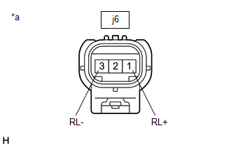
(c) Disconnect the j6 rear skid control sensor wire LH No. 1 connector.
(d) Check both the connector case and the terminals for deformation and corrosion.
OK:
No deformation or corrosion.
(e) Turn the engine switch on (IG).
(f) Measure the voltage according to the value(s) in the table below.
Standard Voltage:
| Tester Connection | Condition | Specified Condition |
|---|---|---|
| j6-1 (RL+) - j6-3 (RL-) | Engine switch on (IG) | 11 to 14 V |
| OK | | REPLACE REAR SKID CONTROL SENSOR WIRE LH NO. 1 |
|
| 15. | CHECK HARNESS AND CONNECTOR (SENSOR GROUND CIRCUIT) |
| (a) Turn the engine switch off. |
|
(b) Make sure that there is no looseness at the locking part and the connecting part of the connectors.
OK:
The connector is securely connected.
(c) Disconnect the T8 rear skid control sensor wire LH No. 2 connector.
(d) Check both the connector case and the terminals for deformation and corrosion.
OK:
No deformation or corrosion.
(e) Turn the engine switch on (IG).
(f) Measure the voltage according to the value(s) in the table below.
Standard Voltage:
| Tester Connection | Condition | Specified Condition |
|---|---|---|
| T8-3 (RL+) - T8-1 (RL-) | Engine switch on (IG) | 11 to 14 V |
| OK | | REPLACE REAR SKID CONTROL SENSOR WIRE LH NO. 2 |
|
| 16. | CHECK HARNESS AND CONNECTOR (SENSOR GROUND CIRCUIT) |
| (a) Turn the engine switch off. |
|
(b) Make sure that there is no looseness at the locking part and the connecting part of the connectors.
OK:
The connector is securely connected.
(c) Disconnect the A41 skid control ECU (brake actuator assembly) connector.
(d) Check both the connector case and the terminals for deformation and corrosion.
OK:
No deformation or corrosion.
(e) Measure the voltage according to the value(s) in the table below.
Standard Voltage:
| Tester Connection | Condition | Specified Condition |
|---|---|---|
| T8-1 (RL-) - Body ground | Always | Below 1.5 V |
| NG | | REPAIR OR REPLACE HARNESS OR CONNECTOR |
|
| 17. | CHECK HARNESS AND CONNECTOR (REAR SKID CONTROL SENSOR WIRE LH NO. 2 - BRAKE ACTUATOR ASSEMBLY) |
(a) Measure the resistance according to the value(s) in the table below.
Standard Resistance:
| Tester Connection | Condition | Specified Condition |
|---|---|---|
| T8-3 (RL+) or A41-5 (RL+) - T8-1 (RL-) or A41-4 (RL-) | Always | 10 kΩ or higher |
| OK | | REPLACE BRAKE ACTUATOR ASSEMBLY |
| NG | | REPAIR OR REPLACE HARNESS OR CONNECTOR |
 Right Front Wheel Speed Sensor Signal Stuck Low (C050623)
DESCRIPTION Refer to DTC C05061F. Click here DTC No. Detection Item DTC Detection Condition Trouble Area C050623 Right Front Wheel Speed Sensor Signal Stuck Low Any of the following ...
 Left Rear Wheel Speed Sensor Circuit Short to Ground or Open (C050C14)
DESCRIPTION Refer to DTC C050C1F. Click here DTC No. Detection Item DTC Detection Condition Trouble Area C050C14 Left Rear Wheel Speed Sensor Circuit Short to Ground or Open An open ...
Other materials:
Lexus RX (RX 350L, RX450h) 2016-2026 Repair Manual > Seat Heater Control(for Rear Side): Installation
INSTALLATION CAUTION / NOTICE / HINT CAUTION: Wear protective gloves. Sharp areas on the seat frame may injure your hands. PROCEDURE 1. INSTALL SEAT HEATER CONTROL SUB-ASSEMBLY (w/o Rear No. 2 Seat) (a) for 60/40 Split Seat Type RH Side: (1) Engage the 2 clamps to install the seat heater control sub ...
Lexus RX (RX 350L, RX450h) 2016-2026 Repair Manual > Oil Pump: Inspection
INSPECTION PROCEDURE 1. INSPECT FRONT OIL PUMP BODY SUB-ASSEMBLY (a) Turn the front oil pump drive gear with 2 screwdrivers and check that it rotates smoothly. NOTICE: Be careful not to damage the lip of the front oil pump oil seal. 2. INSPECT CLEARANCE OF FRONT OIL PUMP BODY AND GEAR ...
Lexus RX (RX 350L, RX450h) 2016-{YEAR} Owners Manual
- For your information
- Pictorial index
- For safety and security
- Instrument cluster
- Operation of each component
- Driving
- Lexus Display Audio system
- Interior features
- Maintenance and care
- When trouble arises
- Vehicle specifications
- For owners
Lexus RX (RX 350L, RX450h) 2016-{YEAR} Repair Manual

0.0126