Lexus RX (RX 350L, RX450h) 2016-2026 Repair Manual: Installation
INSTALLATION
PROCEDURE
1. INSTALL BRAKE PEDAL SUPPORT ASSEMBLY
(a) Install the brake pedal support assembly with the 4 nuts.
Torque:
14 N·m {143 kgf·cm, 10 ft·lbf}
(b) Install the brake pedal support assembly to the instrument panel reinforcement assembly with the 2 bolts.
Torque:
19.1 N·m {195 kgf·cm, 14 ft·lbf}
(c) Connect the connector and engage the clamp.
2. INSTALL PUSH ROD PIN
(a) Apply lithium soap base glycol grease to the push rod pin.
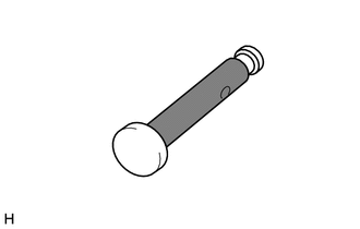
.png) | Lithium Soap Base Glycol Grease |
| (b) Connect the brake master cylinder push rod clevis to the brake pedal support assembly with the push rod pin, and install a new clip as shown in the illustration. NOTICE: Be sure to install the push rod pin in the correct direction. |
|
.png)
3. INSTALL BRAKE PEDAL RETURN SPRING
(a) Install the brake pedal return spring to the instrument panel reinforcement assembly and push rod pin as shown in the illustration.
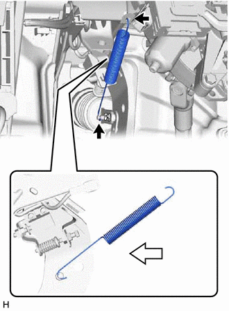
.png) | Front |
4. INSTALL STOP LIGHT SWITCH ASSEMBLY
Click here .gif)
5. INSTALL LOWER NO. 1 INSTRUMENT PANEL AIRBAG ASSEMBLY
Click here
6. INSPECT AND ADJUST BRAKE PEDAL
Click here
 Reassembly
REASSEMBLY PROCEDURE 1. INSTALL BRAKE PEDAL PAD (a) Install the brake pedal pad to the brake pedal sub-assembly. 2. INSTALL BRAKE PEDAL BUSHING (a) Apply lithium soap base glycol grease to 2 new brake ...
 Brake System
...
Other materials:
Lexus RX (RX 350L, RX450h) 2016-2026 Repair Manual > Security Horn Assembly (for Built-in Battery Type): Removal
REMOVAL CAUTION / NOTICE / HINT The necessary procedures (adjustment, calibration, initialization or registration) that must be performed after parts are removed and installed, or replaced during theft warning siren assembly removal/installation are shown below. Necessary Procedures after parts remo ...
Lexus RX (RX 350L, RX450h) 2016-2026 Repair Manual > Intelligent Clearance Sonar System: G Sensor Failure (C1647)
DESCRIPTION The clearance warning sonar ECU assembly communicates with the airbag sensor assembly*1 or yaw rate and acceleration sensor*2 via CAN communication, and if it is determined that the airbag sensor assembly*1 or yaw rate and acceleration sensor*2 is malfunctioning, DTC C1647 is stored. ...
Lexus RX (RX 350L, RX450h) 2016-{YEAR} Owners Manual
- For your information
- Pictorial index
- For safety and security
- Instrument cluster
- Operation of each component
- Driving
- Lexus Display Audio system
- Interior features
- Maintenance and care
- When trouble arises
- Vehicle specifications
- For owners
Lexus RX (RX 350L, RX450h) 2016-{YEAR} Repair Manual

0.0102