Lexus RX (RX 350L, RX450h) 2016-2026 Repair Manual: Installation
INSTALLATION
CAUTION / NOTICE / HINT
HINT:
- Use the same procedure for the RH side and LH side.
- The following procedure is for the LH side.
PROCEDURE
1. INSTALL FRONT AXLE HUB SUB-ASSEMBLY
(a) Secure the steering knuckle between aluminum plates in a vise.
NOTICE:
Do not overtighten the vise.
(b) Install the front axle hub sub-assembly and front disc brake dust cover to the steering knuckle with the 4 bolts.
Torque:
96 N·m {979 kgf·cm, 71 ft·lbf}
NOTICE:
- Be careful not to damage the speed sensor rotor or contact surfaces.
- Do not allow foreign matter to contact the speed sensor rotor or contact surfaces.
2. INSTALL FRONT AXLE ASSEMBLY
(a) Apply 0.1 to 0.3 g (0.00353 to 0.0105 oz) of Toyota Body Grease W to each of the 4 areas shown in the illustration.
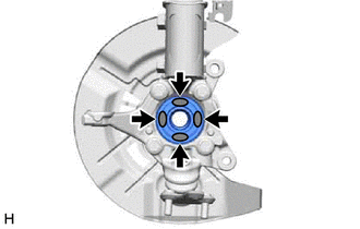
.png) | Toyota Body Grease W |
(b) Install the front axle assembly to the front shock absorber assembly with the 2 bolts and 2 nuts.
Torque:
290 N·m {2957 kgf·cm, 214 ft·lbf}
NOTICE:
- Do not apply lubricants to the steering knuckle and shock absorber contact surfaces.
- When installing the nuts, keep the bolts from rotating.
HINT:
Insert the bolts from the front of the vehicle.
3. INSTALL FRONT DRIVE SHAFT ASSEMBLY
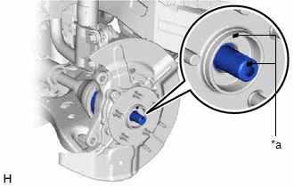
| (a) Align the matchmarks on the front drive shaft assembly and front axle hub sub-assembly, and connect the front drive shaft assembly to the front axle assembly. NOTICE:
|
|
4. CONNECT FRONT LOWER NO. 1 SUSPENSION ARM SUB-ASSEMBLY
(a) Connect the front lower No. 1 suspension arm sub-assembly to the front lower ball joint assembly with the bolt and 2 nuts.
Torque:
92 N·m {938 kgf·cm, 68 ft·lbf}
5. CONNECT TIE ROD ASSEMBLY
Click here .gif)
6. INSTALL FRONT DISC
Click here
7. INSTALL FRONT DISC BRAKE CALIPER ASSEMBLY
Click here
8. INSTALL FRONT AXLE SHAFT NUT
(a) Clean the threaded parts on the front drive shaft assembly and a new front axle shaft nut using non-residue solvent.
NOTICE:
- Be sure to perform this work even when using a new front drive shaft assembly.
- Keep the threaded parts free of oil and foreign matter.
(b) Using a 30 mm deep socket wrench, while applying the brakes, temporarily install the front axle shaft nut.
Torque:
294 N·m {2998 kgf·cm, 217 ft·lbf}
NOTICE:
Stake the front axle shaft nut after inspecting for looseness and runout in the following steps.
HINT:
Keep depressing the brake pedal to prevent the front drive shaft from rotating.
9. SEPARATE FRONT DISC BRAKE CALIPER ASSEMBLY
Click here
10. REMOVE FRONT DISC
Click here
11. INSPECT FRONT AXLE HUB BEARING LOOSENESS
Click here
12. INSPECT FRONT AXLE HUB RUNOUT
Click here
13. INSTALL FRONT DISC
Click here
14. INSTALL FRONT DISC BRAKE CALIPER ASSEMBLY
Click here
15. INSTALL FRONT SPEED SENSOR (w/o AVS)
| (a) Install the front speed sensor to the steering knuckle with the bolt. Torque: 8.5 N·m {87 kgf·cm, 75 in·lbf} NOTICE:
|
|

(b) Engage the 2 claws to install the sensor clamp.
16. INSTALL FRONT SPEED SENSOR (w/ AVS)
| (a) Install the front speed sensor to the front shock absorber assembly and steering knuckle with the 2 bolts. Torque: Bolt (A) : 8.5 N·m {87 kgf·cm, 75 in·lbf} Bolt (B) : 10 N·m {102 kgf·cm, 7 ft·lbf} NOTICE:
|
|
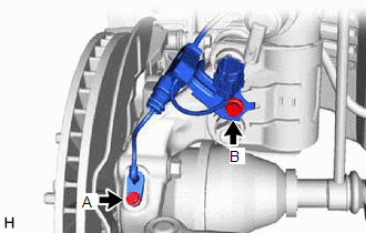
| (b) Connect the AVS connector to the absorber control actuator. |
|
.png)
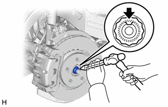
17. STAKE FRONT AXLE SHAFT NUT
| (a) Using a chisel and hammer, stake the front axle shaft nut. |
|
18. INSTALL FRONT WHEEL
Click here
19. INSPECT AND ADJUST FRONT WHEEL ALIGNMENT
Click here
20. CHECK FOR SPEED SENSOR SIGNAL
Click here
 Removal
REMOVAL CAUTION / NOTICE / HINT The necessary procedures (adjustment, calibration, initialization, or registration) that must be performed after parts are removed and installed, or replaced during fro ...
 Front Axle Hub Bolt
ComponentsCOMPONENTS ILLUSTRATION *1 FRONT AXLE HUB BOLT *2 FRONT DISC *3 FRONT DISC BRAKE CALIPER ASSEMBLY - - Tightening torque for "Major areas involving basic vehicle pe ...
Other materials:
Lexus RX (RX 350L, RX450h) 2016-2026 Repair Manual > Sliding Roof Housing (for Panoramic Moon Roof): Disassembly
DISASSEMBLY PROCEDURE 1. REMOVE ROOM LIGHT BRACKET (a) Remove the 4 nuts. (b) Disengage the clamp to remove the room light bracket. 2. REMOVE NO. 2 ROOF WIRE (a) Disconnect the connector. (b) Disengage the claw to remove the No. 2 roof wire. 3. REMOVE SLIDING ROOF DRIVE ...
Lexus RX (RX 350L, RX450h) 2016-2026 Owners Manual > Lexus Display
Audio system: Using the audio system
Selecting the audio
source
Switching between audio sources, such as the radio and CD, is explained
in
this section.
Changing audio source
1. Press the "AUDIO" button to display the "Source" screen.
If the "Source" screen is not displayed, press the button again.
2. Select the desired audi ...
Lexus RX (RX 350L, RX450h) 2016-{YEAR} Owners Manual
- For your information
- Pictorial index
- For safety and security
- Instrument cluster
- Operation of each component
- Driving
- Lexus Display Audio system
- Interior features
- Maintenance and care
- When trouble arises
- Vehicle specifications
- For owners
Lexus RX (RX 350L, RX450h) 2016-{YEAR} Repair Manual

0.0096