Lexus RX (RX 350L, RX450h) 2016-2026 Repair Manual: Removal
REMOVAL
CAUTION / NOTICE / HINT
The necessary procedures (adjustment, calibration, initialization, or registration) that must be performed after parts are removed and installed, or replaced during front axle hub sub-assembly removal/installation are shown below.
Necessary Procedures After Parts Removed/Installed/Replaced| Replaced Part or Performed Procedure | Necessary Procedure | Effect/Inoperative Function when Necessary Procedure not Performed | Link |
|---|---|---|---|
| Front wheel alignment adjustment | Calibration |
| |
HINT:
- Use the same procedure for the RH side and LH side.
- The following procedure is for the LH side.
PROCEDURE
1. REMOVE FRONT WHEEL
Click here .gif)
2. REMOVE FRONT AXLE SHAFT NUT
Click here
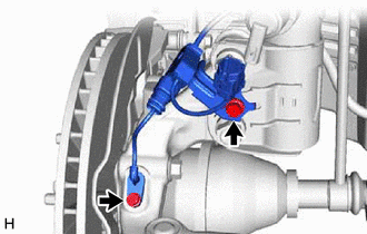
3. SEPARATE FRONT SPEED SENSOR (w/o AVS)
| (a) Disengage the 2 claws and separate the sensor clamp. |
|
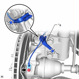
(b) Remove the bolt and separate the front speed sensor from the steering knuckle.
NOTICE:
- Prevent foreign matter from contacting the sensor tip.
- Be careful not to damage the front speed sensor.
- Clean the speed sensor installation hole and the contact surfaces every time the speed sensor is removed.
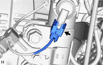
4. SEPARATE FRONT SPEED SENSOR (w/ AVS)
| (a) Disconnect the AVS connector from the absorber control actuator. |
|
| (b) Remove the 2 bolts and separate the front speed sensor from the front shock absorber assembly and steering knuckle. NOTICE:
|
|
5. SEPARATE TIE ROD ASSEMBLY
Click here
6. SEPARATE FRONT DISC BRAKE CALIPER ASSEMBLY
Click here
7. REMOVE FRONT DISC
Click here
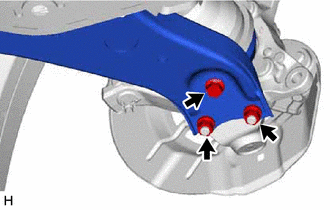
8. SEPARATE FRONT LOWER NO. 1 SUSPENSION ARM SUB-ASSEMBLY
| (a) Remove the bolt, 2 nuts and separate the front lower No. 1 suspension arm sub-assembly from the front lower ball joint assembly. |
|
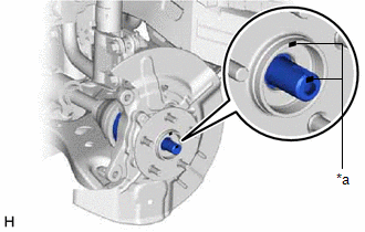
9. SEPARATE FRONT DRIVE SHAFT ASSEMBLY
| (a) Put matchmarks on the front drive shaft assembly and the front axle hub sub-assembly. |
|
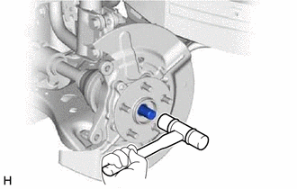
| (b) Using a plastic hammer, separate the front drive shaft assembly from the front axle assembly. NOTICE:
HINT: If it is difficult to separate the front drive shaft assembly from the front axle assembly, tap the end of the front drive shaft assembly using a brass bar and a hammer. |
|
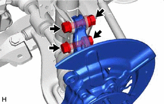
10. REMOVE FRONT AXLE ASSEMBLY
| (a) Remove the 2 bolts, 2 nuts and front axle assembly from the front shock absorber assembly. NOTICE: When removing the nuts, keep the bolts from rotating. |
|
11. REMOVE FRONT AXLE HUB SUB-ASSEMBLY
| (a) Secure the front axle assembly between aluminum plates in a vise. NOTICE: Do not overtighten the vise. |
|
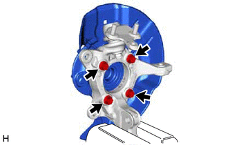
(b) Remove the 4 bolts, front axle hub sub-assembly and front disc brake dust cover from the steering knuckle.
NOTICE:
- Do not drop the front axle hub sub-assembly.
- Be careful not to damage the speed sensor rotor or contact surfaces.
- Do not allow foreign matter to contact the speed sensor rotor or contact surfaces.
 On-vehicle Inspection
ON-VEHICLE INSPECTION CAUTION / NOTICE / HINT HINT:
Use the same procedure for the RH side and LH side.
The following procedure is for the LH side.
PROCEDURE 1. REMOVE FRONT WHEEL Click here ...
 Installation
INSTALLATION CAUTION / NOTICE / HINT HINT:
Use the same procedure for the RH side and LH side.
The following procedure is for the LH side.
PROCEDURE 1. INSTALL FRONT AXLE HUB SUB-ASSEMBLY (a) ...
Other materials:
Lexus RX (RX 350L, RX450h) 2016-2026 Repair Manual > Can Communication System: Suspension Control ECU Communication Stop Mode
DESCRIPTION Detection Item Symptom Trouble Area Suspension Control ECU Communication Stop Mode Either condition is met:
"Suspension Control (Air Suspension)" is not displayed on the CAN Bus Check screen of the Techstream.
Click here
Communication system DTCs (DTCs that start w ...
Lexus RX (RX 350L, RX450h) 2016-2026 Repair Manual > Sfi System: Camshaft Position "A" - Timing Over-Advanced or System Performance Bank 1 Mechanical Failure (P001107,P002107)
DESCRIPTION Refer to DTC P001013. Click here DTC No. Detection Item DTC Detection Condition Trouble Area MIL Memory Note P001107 Camshaft Position "A" - Timing Over-Advanced or System Performance Bank 1 Mechanical Failure 10° CA or greater camshaft timing gear assembly (ban ...
Lexus RX (RX 350L, RX450h) 2016-{YEAR} Owners Manual
- For your information
- Pictorial index
- For safety and security
- Instrument cluster
- Operation of each component
- Driving
- Lexus Display Audio system
- Interior features
- Maintenance and care
- When trouble arises
- Vehicle specifications
- For owners
Lexus RX (RX 350L, RX450h) 2016-{YEAR} Repair Manual

0.0123