Lexus RX (RX 350L, RX450h) 2016-2026 Repair Manual: Installation
INSTALLATION
CAUTION / NOTICE / HINT
HINT:
- Use the same procedure for the RH side and LH side.
- The following procedure is for the LH side.
PROCEDURE
1. INSTALL LOWER CONTROL ARM PIN (for TMMC Made)
| (a) Secure the rear axle carrier sub-assembly in a vise using aluminum plates. NOTICE: Do not overtighten the vise. |
|
.png)
(b) Using SST, install a new lower control arm pin to the rear axle carrier sub-assembly as shown in the illustration.
SST: 09650-17011
2. TEMPORARILY INSTALL REAR AXLE CARRIER SUB-ASSEMBLY
| (a) Secure the rear axle carrier sub-assembly in a vise using aluminum plates. NOTICE: Do not overtighten the vise. |
|
.png)
(b) Using a brass bar and a hammer, push out the bushing until it is positioned as shown in the illustration.
HINT:
Pushing out the bushing makes it easier to install the rear axle carrier sub-assembly.
| (c) Temporarily install the rear axle carrier sub-assembly to the rear No. 1 suspension arm assembly with the spacer and nut (A). NOTICE: Fully tighten the nut (A) after stabilizing the suspension. |
|
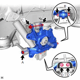
(d) Install the rear axle carrier sub-assembly to the rear No. 2 suspension arm assembly with the bolt (B) and nut.
Torque:
100 N·m {1020 kgf·cm, 74 ft·lbf}
NOTICE:
- Insert the bolt with the threaded end facing the front of the vehicle.
- Because the nut has its own stopper, do not turn the nut. Tighten the bolt with the nut secured.
(e) Install the rear axle carrier sub-assembly to the rear upper control arm assembly with the bolt (C) and nut.
Torque:
145 N·m {1479 kgf·cm, 107 ft·lbf}
NOTICE:
- Insert the bolt with the threaded end facing the rear of the vehicle.
- Because the nut has its own stopper, do not turn the nut. Tighten the bolt with the nut secured.
(f) Install the rear axle carrier sub-assembly to the rear lower shock absorber bracket sub-assembly with the 2 bolts (D).
Torque:
100 N·m {1020 kgf·cm, 74 ft·lbf}
(g) Slowly lower the rear No. 2 suspension arm assembly.
3. INSTALL REAR TRAILING ARM ASSEMBLY
Click here .gif)
4. INSTALL REAR AXLE HUB AND BEARING ASSEMBLY
Click here
5. INSTALL REAR SPEED SENSOR
| (a) Install the rear speed sensor to the rear trailing arm assembly with the bolt. Torque: 8.5 N·m {87 kgf·cm, 75 in·lbf} NOTICE: Do not twist the rear speed sensor when installing it. |
|
.png)
| (b) Install the rear speed sensor to the rear axle carrier sub-assembly with the bolt. Torque: 8.5 N·m {87 kgf·cm, 75 in·lbf} NOTICE: Do not twist the rear speed sensor when installing it. |
|
.png)
6. INSTALL NO. 2 PARKING BRAKE WIRE ASSEMBLY
| (a) Install the No. 2 parking brake wire assembly to the rear trailing arm assembly with the 3 bolts. Torque: Bolt (A) : 15 N·m {153 kgf·cm, 11 ft·lbf} Bolt (B) : 8.5 N·m {87 kgf·cm, 75 in·lbf} |
|
.png)
7. INSTALL REAR DISC
Click here
8. INSTALL REAR DISC BRAKE CALIPER ASSEMBLY
Click here
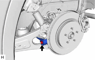
9. INSTALL REAR FLEXIBLE HOSE
(a) Install the rear flexible hose to the rear upper control arm assembly with the bolt.
Torque:
18.8 N·m {192 kgf·cm, 14 ft·lbf}
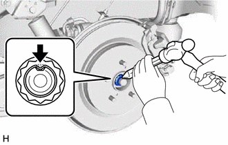
10. INSTALL REAR AXLE SHAFT NUT
(a) Clean the threaded parts on the rear drive shaft assembly and a new rear axle shaft nut using non-residue solvent.
NOTICE:
- Be sure to perform this work even when using a new rear drive shaft assembly.
- Keep the threaded parts free of oil and foreign matter.
(b) Using a 30 mm deep socket wrench, temporarily install the rear axle shaft nut.
Torque:
294 N·m {2998 kgf·cm, 217 ft·lbf}
HINT:
Keep depressing the brake pedal to prevent the rear drive shaft assembly from rotating.
| (c) Using a chisel and hammer, stake the rear axle shaft nut. |
|
11. STABILIZE SUSPENSION
Click here
12. INSTALL REAR NO. 1 SUSPENSION ARM ASSEMBLY
| (a) Install the rear No. 1 suspension arm assembly with the nut. Torque: 145 N·m {1479 kgf·cm, 107 ft·lbf} |
|
13. INSTALL REAR SUSPENSION ARM COVER
Click here
14. INSTALL REAR WHEEL
Click here
15. INSPECT AND ADJUST REAR WHEEL ALIGNMENT
Click here
16. CHECK FOR SPEED SENSOR SIGNAL
Click here
17. PERFORM INITIALIZATION
| |
| Parking Assist Monitor System | for Initialization: for Calibration: |
| Panoramic View Monitor System | for Initialization: for Calibration: |
| Lighting System (w/ Automatic Headlight Beam Level Control System) | |
 Removal
REMOVAL CAUTION / NOTICE / HINT The necessary procedures (adjustment, calibration, initialization, or registration) that must be performed after parts are removed and installed, or replaced during rea ...
 Rear Axle Hub
...
Other materials:
Lexus RX (RX 350L, RX450h) 2016-2026 Repair Manual > Navigation System: Problem Symptoms Table
PROBLEM SYMPTOMS TABLE NOTICE: Depending on the parts that are replaced during vehicle inspection or maintenance, performing initialization, registration or calibration may be needed. Refer to Precaution for Navigation System. Click here HINT:
Use the table below to help determine the cause of ...
Lexus RX (RX 350L, RX450h) 2016-2026 Repair Manual > Rear Power Seat Control System(for Second Row): Rear Power Seat Switch Circuit
DESCRIPTION HINT: The rear power seat switch is a collective term for the rear power seat switch RH and the rear power seat switch LH. When the rear power seat switch is operated, a recline signal is sent to the fold seat control ECU. The fold seat control ECU operates the reclining motor according ...
Lexus RX (RX 350L, RX450h) 2016-{YEAR} Owners Manual
- For your information
- Pictorial index
- For safety and security
- Instrument cluster
- Operation of each component
- Driving
- Lexus Display Audio system
- Interior features
- Maintenance and care
- When trouble arises
- Vehicle specifications
- For owners
Lexus RX (RX 350L, RX450h) 2016-{YEAR} Repair Manual

0.0119