Lexus RX (RX 350L, RX450h) 2016-2026 Repair Manual: Replacement
REPLACEMENT
CAUTION / NOTICE / HINT
The necessary procedures (adjustment, calibration, initialization, or registration) that must be performed after parts are removed and installed, or replaced during diaphragm oil seal replacement are shown below.
Necessary Procedures After Parts Removed/Installed/Replaced| Replaced Part or Performed Procedure | Necessary Procedure | Effect/Inoperative Function when Necessary Procedure not Performed | Link |
|---|---|---|---|
| Rear wheel alignment adjustment | Calibration |
| |
| Suspension, tires, etc. (The vehicle height changes because of suspension or tire replacement) |
|
| |
| Rear television camera assembly optical axis (Back camera position setting) | Parking assist monitor system | for Initialization: for Calibration: | |
| Panoramic view monitor system | for Initialization: for Calibration: | |
| Initialize No. 1 headlight ECU sub-assembly LH | Lighting System (w/ Automatic Headlight Beam Level Control System) | | |
| Gas leaks from exhaust system | Inspection after repair |
| |
PROCEDURE
1. REMOVE NO. 2 REAR DIFFERENTIAL SUPPORT
Click here .gif)
2. SEPARATE ELECTRO MAGNETIC CONTROL COUPLING WIRE HARNESS
Click here
3. REMOVE ELECTRO MAGNETIC CONTROL COUPLING SUB-ASSEMBLY
Click here
4. REMOVE TRANSMISSION COUPLING CONICAL SPRING WASHER
Click here
5. REMOVE TRANSMISSION COUPLING SPACER
Click here
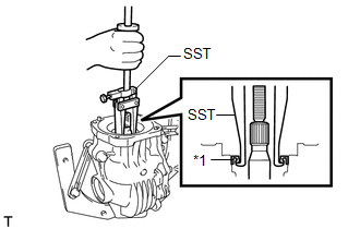
6. REMOVE DIAPHRAGM OIL SEAL
| (a) Using SST, remove the diaphragm oil seal from the rear differential carrier assembly. SST: 09308-00010 |
|
7. INSTALL DIAPHRAGM OIL SEAL
| (a) Using SST and a press, install a new diaphragm oil seal into the rear differential carrier assembly. SST: 09506-35010 SST: 09554-22010 NOTICE:
Standard Distance (A): 0.7 to 1.3 mm (0.0276 to 0.0511 in.) |
|
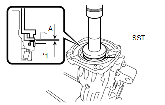
(b) Apply a light coat of MP grease to the lip of the new diaphragm oil seal.
8. INSTALL TRANSMISSION COUPLING SPACER
Click here
9. INSTALL TRANSMISSION COUPLING CONICAL SPRING WASHER
Click here
10. INSTALL ELECTRO MAGNETIC CONTROL COUPLING SUB-ASSEMBLY
Click here
11. INSTALL ELECTRO MAGNETIC CONTROL COUPLING WIRE HARNESS
Click here
12. TEMPORARILY INSTALL NO. 2 REAR DIFFERENTIAL SUPPORT
Click here
 Components
COMPONENTS ILLUSTRATION *1 DIAPHRAGM OIL SEAL *2 ELECTRO MAGNETIC CONTROL COUPLING SUB-ASSEMBLY *3 ELECTRO MAGNETIC CONTROL COUPLING WIRE HARNESS *4 TRANSMISSION COUPLING CONICAL S ...

Other materials:
Lexus RX (RX 350L, RX450h) 2016-2026 Repair Manual > Lighting System (w/ Automatic Headlight Beam Level Control System): Front Fog Light Circuit
DESCRIPTION The main body ECU (multiplex network body ECU) controls the front fog lights. WIRING DIAGRAM CAUTION / NOTICE / HINT NOTICE:
Inspect the fuses for circuits related to this system before performing the following procedure.
Before replacing the main body ECU (multiplex network body E ...
Lexus RX (RX 350L, RX450h) 2016-2026 Repair Manual > Vehicle Stability Control System: Control Module Communication Bus "B" Off Bus Off (U007488,U010087,U010187,U012587,U012687,U015187)
DESCRIPTION The skid control ECU (brake actuator assembly) receives signals from the ECM, steering angle sensor, yaw rate and acceleration sensor (for TFT Meter Type) and airbag sensor assembly via CAN communication. DTC No. Detection Item DTC Detection Condition Trouble Area U007488 ...
Lexus RX (RX 350L, RX450h) 2016-{YEAR} Owners Manual
- For your information
- Pictorial index
- For safety and security
- Instrument cluster
- Operation of each component
- Driving
- Lexus Display Audio system
- Interior features
- Maintenance and care
- When trouble arises
- Vehicle specifications
- For owners
Lexus RX (RX 350L, RX450h) 2016-{YEAR} Repair Manual

0.012