Lexus RX (RX 350L, RX450h) 2016-2026 Repair Manual: Buzzer Circuit Short to Battery (C1A4A12)
DESCRIPTION
If the forward recognition camera detects a short to +B in the buzzer circuit, it will store DTC C1A4A12.
| DTC No. | Detection Item | DTC Detection Condition | Trouble Area |
|---|---|---|---|
| C1A4A12 | Buzzer Circuit Short to Battery | While the skid control buzzer assembly is sounding, the forward recognition camera detects a short to +B in the buzzer circuit for 3 seconds or more. |
|
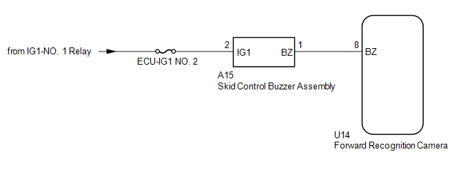
WIRING DIAGRAM
CAUTION / NOTICE / HINT
NOTICE:
- Inspect the fuses for circuits related to this system before performing the following procedure.
- When replacing the forward recognition camera, always replace it with a new one. If a forward recognition camera which was installed to another vehicle is used, the information stored in the forward recognition camera will not match the information from the vehicle. As a result, a DTC may be stored.
-
If the forward recognition camera has been replaced with a new one, be sure to perform forward recognition camera adjustment.
HINT:
Forward recognition camera adjustment can be performed by using either One Time Recognition or Sequential Recognition.
One Time Recognition: Click here
.gif)
Sequential Recognition: Click here
PROCEDURE
| 1. | CHECK FOR DTCs |
(a) Clear the DTCs.
Chassis > Front Recognition Camera > Clear DTCs(b) Perform the Active Test according to the display on the Techstream.
NOTICE:
Perform the Active Test for 3 seconds or more.
HINT:
Performing the Active Test for 3 seconds or more causes DTC C1A4A12 to be stored if the DTC detection conditions are met.
Body Electrical > Pre-Collision System > Active Test| Tester Display | Measurement Item | Control Range | Diagnostic Note |
|---|---|---|---|
| PCS Warning Buzzer | Sounds the skid control buzzer | Active / Not Active | Test possible with engine switch on (IG), vehicle stopped |
| Tester Display |
|---|
| PCS Warning Buzzer |
(c) Check for DTCs.
Chassis > Front Recognition Camera > Trouble Codes| Result | Proceed to |
|---|---|
| DTC C1A4A12 is not output | A |
| DTC C1A4A12 is output | B |
| A | .gif) | USE SIMULATION METHOD TO CHECK |
|
.gif)
| 2. | CHECK HARNESS AND CONNECTOR (SKID CONTROL BUZZER ASSEMBLY - FORWARD RECOGNITION CAMERA) |
(a) Disconnect the A15 skid control buzzer assembly connector.
(b) Disconnect the U14 forward recognition camera connector.
(c) Measure the voltage according to the value(s) in the table below.
Standard Voltage:
| Tester Connection | Switch Condition | Specified Condition |
|---|---|---|
| A15-1 (BZ) or U14-8 (BZ) - Body ground | Engine switch off | Below 1 V |
| NG | | REPAIR OR REPLACE HARNESS OR CONNECTOR |
|
| 3. | INSPECT SKID CONTROL BUZZER ASSEMBLY |
(a) Remove the skid control buzzer assembly.
Click here
(b) Inspect the skid control buzzer assembly.
Click here
| OK | | REPLACE FORWARD RECOGNITION CAMERA |
| NG | | REPLACE SKID CONTROL BUZZER ASSEMBLY |
 Control Module Internal Temperature Sensor "A" Circuit Circuit Voltage Out of Range (C10001C,C10051C,C100A62,C1A9346,C1A9445,C1A9447,C1A9487-C1A961C)
DESCRIPTION When an internal malfunction is detected in the forward recognition camera, these DTCs are stored. DTC No. Detection Item DTC Detection Condition Trouble Area C10001C Contro ...
 Buzzer Circuit Short to Ground or Open (C1A4A14)
DESCRIPTION If the forward recognition camera detects an open or short to ground in the buzzer circuit, it will store DTC C1A4A14. DTC No. Detection Item DTC Detection Condition Trouble Area ...
Other materials:
Lexus RX (RX 350L, RX450h) 2016-2026 Repair Manual > Smart Access System With Push-button Start (for Start Function): ACC Monitor Malfunction (B2274)
DESCRIPTION This DTC is stored when a malfunction in the ACC output circuit is detected. The ACC output circuit is the circuit between terminal ACCD of the certification ECU (smart key ECU assembly) and the ACC relay. DTC No. Detection Item DTC Detection Condition Trouble Area Note B2 ...
Lexus RX (RX 350L, RX450h) 2016-2026 Owners Manual > For safe use: Front passenger occupant
classification system
Your vehicle is equipped with a front passenger occupant classification
system.
This system detects the conditions of the front passenger seat and activates
or deactivates the devices for the front passenger.
SRS warning light
Seat belt reminder light
"AIR BAG OFF" indicator light
...
Lexus RX (RX 350L, RX450h) 2016-{YEAR} Owners Manual
- For your information
- Pictorial index
- For safety and security
- Instrument cluster
- Operation of each component
- Driving
- Lexus Display Audio system
- Interior features
- Maintenance and care
- When trouble arises
- Vehicle specifications
- For owners
Lexus RX (RX 350L, RX450h) 2016-{YEAR} Repair Manual

0.011