Lexus RX (RX 350L, RX450h) 2016-2026 Repair Manual: Buzzer Circuit Short to Ground or Open (C1A4A14)
DESCRIPTION
If the forward recognition camera detects an open or short to ground in the buzzer circuit, it will store DTC C1A4A14.
| DTC No. | Detection Item | DTC Detection Condition | Trouble Area |
|---|---|---|---|
| C1A4A14 | Buzzer Circuit Short to Ground or Open | The forward recognition camera detects an open or short to ground in the buzzer circuit for 2 seconds or more. |
|
WIRING DIAGRAM
.png)
CAUTION / NOTICE / HINT
NOTICE:
- Inspect the fuses for circuits related to this system before performing the following procedure.
- When replacing the forward recognition camera, always replace it with a new one. If a forward recognition camera which was installed to another vehicle is used, the information stored in the forward recognition camera will not match the information from the vehicle. As a result, a DTC may be stored.
-
If the forward recognition camera has been replaced with a new one, be sure to perform forward recognition camera adjustment.
HINT:
Forward recognition camera adjustment can be performed by using either One Time Recognition or Sequential Recognition.
One Time Recognition: Click here
.gif)
Sequential Recognition: Click here
PROCEDURE
| 1. | CHECK FOR DTCs |
(a) Clear the DTCs.
Chassis > Front Recognition Camera > Clear DTCs(b) Make sure that the DTC detection conditions are met.
HINT:
If the detection conditions are not met, the system cannot detect the malfunction.
(c) Check for DTCs.
Chassis > Front Recognition Camera > Trouble Codes| Result | Proceed to |
|---|---|
| DTC C1A4A14 is not output | A |
| DTC C1A4A14 is output | B |
| A | .gif) | USE SIMULATION METHOD TO CHECK |
|
.gif)
| 2. | CHECK HARNESS AND CONNECTOR (SKID CONTROL BUZZER ASSEMBLY POWER SOURCE CIRCUIT) |
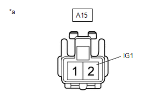
| *a | Front view of wire harness connector (to Skid Control Buzzer Assembly) |
(a) Disconnect the A15 skid control buzzer assembly connector.
(b) Measure the voltage according to the value(s) in the table below.
Standard Voltage:
| Tester Connection | Switch Condition | Specified Condition |
|---|---|---|
| A15-2 (IG1) - Body ground | Engine switch on (IG) | 8 to 16 V |
| Engine switch off | Below 1 V |
| NG | | REPAIR OR REPLACE HARNESS OR CONNECTOR |
|
| 3. | CHECK HARNESS AND CONNECTOR (SKID CONTROL BUZZER ASSEMBLY - FORWARD RECOGNITION CAMERA) |
(a) Disconnect the U14 forward recognition camera connector.
(b) Measure the resistance according to the value(s) in the table below.
Standard Resistance:
| Tester Connection | Condition | Specified Condition |
|---|---|---|
| A15-1 (BZ) - U14-8 (BZ) | Always | Below 1 Ω |
| A15-1 (BZ) or U14-8 (BZ) - Body ground | Always | 10 kΩ higher |
| NG | | REPAIR OR REPLACE HARNESS OR CONNECTOR |
|
| 4. | INSPECT SKID CONTROL BUZZER ASSEMBLY |
(a) Remove the skid control buzzer assembly.
Click here
(b) Inspect the skid control buzzer assembly.
Click here
| OK | | REPLACE FORWARD RECOGNITION CAMERA |
| NG | | REPLACE SKID CONTROL BUZZER ASSEMBLY |
 Buzzer Circuit Short to Battery (C1A4A12)
DESCRIPTION If the forward recognition camera detects a short to +B in the buzzer circuit, it will store DTC C1A4A12. DTC No. Detection Item DTC Detection Condition Trouble Area C1A4A12 ...
 Steering Vibrator System Missing Message (C1A7587)
DESCRIPTION The forward recognition camera communicates with the steering vibration ECU via LIN communication. If a communication error between the forward recognition camera and steering vibration EC ...
Other materials:
Lexus RX (RX 350L, RX450h) 2016-2026 Repair Manual > Wireless Charger Assembly: Components
COMPONENTS ILLUSTRATION *1 CIGAR LIGHTER HOLE COVER *2 CONSOLE BOX ASSEMBLY *3 MOBILE WIRELESS CHARGER CRADLE ASSEMBLY *4 NO. 1 INTERIOR ILLUMINATION LIGHT ASSEMBLY *5 NO. 1 POWER OUTLET SOCKET ASSEMBLY *6 NO. 2 USB CHARGER SOCKET *7 POWER OUTLET SOCKET LENS - ...
Lexus RX (RX 350L, RX450h) 2016-2026 Repair Manual > Vehicle Stability Control System: Right Front Wheel Speed Sensor Signal Stuck Low (C050623)
DESCRIPTION Refer to DTC C05061F. Click here DTC No. Detection Item DTC Detection Condition Trouble Area C050623 Right Front Wheel Speed Sensor Signal Stuck Low Any of the following is detected:
When the +BS terminal voltage is 17.4 V or less at a vehicle speed of 10 km/h (6 mp ...
Lexus RX (RX 350L, RX450h) 2016-{YEAR} Owners Manual
- For your information
- Pictorial index
- For safety and security
- Instrument cluster
- Operation of each component
- Driving
- Lexus Display Audio system
- Interior features
- Maintenance and care
- When trouble arises
- Vehicle specifications
- For owners
Lexus RX (RX 350L, RX450h) 2016-{YEAR} Repair Manual

0.0129