Lexus RX (RX 350L, RX450h) 2016-2026 Repair Manual: Steering Vibrator System Missing Message (C1A7587)
DESCRIPTION
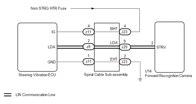
The forward recognition camera communicates with the steering vibration ECU via LIN communication.
If a communication error between the forward recognition camera and steering vibration ECU is detected, DTC C1A7587 is stored.
| DTC No. | Detection Item | DTC Detection Condition | Trouble Area |
|---|---|---|---|
| C1A7587 | Steering Vibrator System Missing Message | While the vehicle is being driven at 5 km/h (4 mph) or more and the lane control system is on, a LIN communication error is detected between the steering vibration ECU and forward recognition camera for approximately 5 minutes or more. |
|
WIRING DIAGRAM
CAUTION / NOTICE / HINT
NOTICE:
- When replacing the forward recognition camera, always replace it with a new one. If a forward recognition camera which was installed to another vehicle is used, the information stored in the forward recognition camera will not match the information from the vehicle. As a result, a DTC may be stored.
-
If the forward recognition camera has been replaced with a new one, be sure to perform forward recognition camera adjustment.
HINT:
Forward recognition camera adjustment can be performed by using either One Time Recognition or Sequential Recognition.
One Time Recognition: Click here
.gif)
Sequential Recognition: Click here
-
The vehicle is equipped with a Supplemental Restraint System (SRS) which includes components such as airbags. Before servicing (including removal or installation of parts), be sure to read the precaution for Supplemental Restraint System.
Click here
PROCEDURE
| 1. | INSPECT SPIRAL CABLE SUB-ASSEMBLY |
(a) Remove the spiral cable sub-assembly.
Click here
(b) Inspect the spiral cable sub-assembly.
Click here
| NG | .gif) | REPLACE SPIRAL CABLE SUB-ASSEMBLY |
|
.gif)
| 2. | INSPECT FORWARD RECOGNITION CAMERA (WAVEFORM) |
(a) Turn the engine switch on (IG).
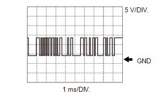
| (b) Using an oscilloscope, measure the waveform at the J29 spiral cable sub-assembly connector. Measurement Condition:
NOTICE: The oscilloscope waveform is for reference only and does not include noise, fluctuations, etc. OK: A waveform similar to that in the illustration can be observed. |
|
| NG | | GO TO STEP 5 |
|
| 3. | CHECK HARNESS AND CONNECTOR (SPIRAL CABLE SUB-ASSEMBLY - POWER SOURCE) |
(a) Measure the voltage according to the value(s) in the table below.
Standard Voltage:
| Tester Connection | Condition | Specified Condition |
|---|---|---|
| J23-4 (BHT) - Body ground | Engine switch on (IG) | 11 to 14 V |
| NG | | REPAIR OR REPLACE HARNESS OR CONNECTOR |
|
| 4. | CHECK HARNESS AND CONNECTOR (SPIRAL CABLE SUB-ASSEMBLY - BODY GROUND) |
(a) Measure the resistance according to the value(s) in the table below.
Standard Resistance:
| Tester Connection | Condition | Specified Condition |
|---|---|---|
| J23-2 (EHT) - Body ground | Always | Below 1 Ω |
| OK | | REPLACE STEERING VIBRATION ECU |
| NG | | REPAIR OR REPLACE HARNESS OR CONNECTOR |
| 5. | CHECK HARNESS AND CONNECTOR (SPIRAL CABLE SUB-ASSEMBLY - FORWARD RECOGNITION CAMERA) |
(a) Disconnect the U14 forward recognition camera connector.
(b) Measure the resistance according to the value(s) in the table below.
Standard Resistance:
| Tester Connection | Condition | Specified Condition |
|---|---|---|
| J29-9 (LDA) - U14-2 (STRV) | Always | Below 1 Ω |
| J29-9 (LDA) or U14-2 (STRV) - Body ground | Engine switch off | 10 kΩ or higher |
| OK | | REPLACE FORWARD RECOGNITION CAMERA |
| NG | | REPAIR OR REPLACE HARNESS OR CONNECTOR |
 Buzzer Circuit Short to Ground or Open (C1A4A14)
DESCRIPTION If the forward recognition camera detects an open or short to ground in the buzzer circuit, it will store DTC C1A4A14. DTC No. Detection Item DTC Detection Condition Trouble Area ...
 Front Recognition Camera Optical Axis Misalignment Malfunction (C1AA800)
DESCRIPTION The forward recognition camera monitors its optical axis status. If it determines that the optical axis alignment has become misaligned, it will store DTC C1AA800. DTC No. Detection I ...
Other materials:
Lexus RX (RX 350L, RX450h) 2016-2026 Repair Manual > Vehicle Stability Control System: Right Rear Wheel Speed Sensor Circuit Short to Battery (C051212)
DESCRIPTION Refer to DTC C05121F. Click here DTC No. Detection Item DTC Detection Condition Trouble Area C051212 Right Rear Wheel Speed Sensor Circuit Short to Battery The speed sensor short signal is ON continuously for 0.5 seconds or more.
Rear speed sensor RH*1
Rear spee ...
Lexus RX (RX 350L, RX450h) 2016-2026 Repair Manual > Can Communication System: Precaution
PRECAUTION NOTICE FOR INITIALIZATION NOTICE: When disconnecting the cable from the negative (-) battery terminal, initialize the following systems after the cable is reconnected. System See Procedure LKA /LDA System Pre-collision System Intelligent Clearance Sonar System Li ...
Lexus RX (RX 350L, RX450h) 2016-{YEAR} Owners Manual
- For your information
- Pictorial index
- For safety and security
- Instrument cluster
- Operation of each component
- Driving
- Lexus Display Audio system
- Interior features
- Maintenance and care
- When trouble arises
- Vehicle specifications
- For owners
Lexus RX (RX 350L, RX450h) 2016-{YEAR} Repair Manual

0.0159