Lexus RX (RX 350L, RX450h) 2016-2026 Repair Manual: Removal
REMOVAL
CAUTION / NOTICE / HINT
HINT:
- Use the same procedure for the RH side and LH side.
- The following procedure is for the LH side.
PROCEDURE
1. REMOVE REAR WHEEL
Click here .gif)
2. REMOVE REAR SUSPENSION ARM COVER
Click here
3. REMOVE REAR AXLE SHAFT NUT (for AWD)
| (a) Using SST and a hammer, release the staked part of the rear axle shaft nut. SST: 09930-00010 NOTICE: Loosen the staked part of the rear axle shaft nut completely, otherwise the threads of the rear drive shaft assembly may be damaged. |
|
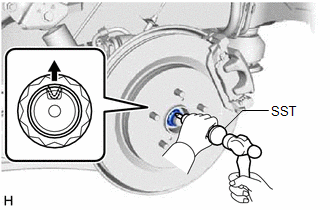
(b) While applying the brakes, remove the rear axle shaft nut.
4. SEPARATE REAR DISC BRAKE CALIPER ASSEMBLY
Click here
5. REMOVE REAR DISC
Click here
6. SEPARATE REAR SKID CONTROL SENSOR WIRE (for 2WD)
Click here
7. SEPARATE REAR SPEED SENSOR (for AWD)
| (a) Remove the bolt and separate the rear speed sensor from the rear axle carrier sub-assembly. NOTICE:
|
|
.png)
8. REMOVE REAR AXLE HUB AND BEARING ASSEMBLY (for 2WD)
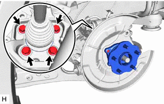
(a) Remove the 4 bolts, rear axle hub and bearing assembly and rear disc brake dust cover sub-assembly from the rear axle carrier sub-assembly.
9. REMOVE REAR AXLE HUB AND BEARING ASSEMBLY (for AWD)
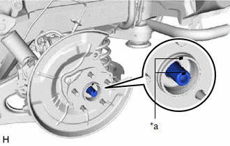
| (a) Put matchmarks on the rear drive shaft assembly and rear axle hub and bearing assembly. |
|
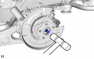
| (b) Using a plastic hammer, separate the rear drive shaft assembly from the rear axle hub and bearing assembly. HINT: If it is difficult to separate the rear drive shaft assembly from the rear axle hub and bearing assembly, tap the end of the rear drive shaft assembly using a brass bar and a hammer. |
|
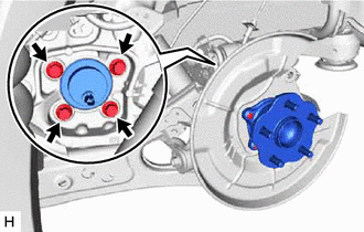
| (c) Remove the 4 bolts, rear axle hub and bearing assembly and rear disc brake dust cover sub-assembly from the rear axle carrier sub-assembly. |
|
 On-vehicle Inspection
ON-VEHICLE INSPECTION CAUTION / NOTICE / HINT HINT:
Use the same procedure for the RH side and LH side.
The following procedure is for the LH side.
PROCEDURE 1. REMOVE REAR WHEEL Click here ...
 Installation
INSTALLATION CAUTION / NOTICE / HINT HINT:
Use the same procedure for the RH side and LH side.
The following procedure is for the LH side.
PROCEDURE 1. INSTALL REAR AXLE HUB AND BEARING ASSEMB ...
Other materials:
Lexus RX (RX 350L, RX450h) 2016-2026 Repair Manual > Front Power Seat Control System (w/ Memory): Operation Check
OPERATION CHECK CHECK POWER SEAT FUNCTION (a) Check the basic functions. *a Slide Function *b Reclining Function *c Lifter Function *d Front Vertical Function *e Lumbar Support Adjustment Function (up - down) (w/ Seat Variable Cushion Switch) *f Lumbar Support Adj ...
Lexus RX (RX 350L, RX450h) 2016-2026 Repair Manual > Sfi System: Throttle Actuator "A" Control System Actuator Stuck Open (P211172,P211173)
DESCRIPTION The throttle actuator is operated by the ECM, and opens and closes the throttle valve using gears. The opening angle of the throttle valve is detected by the throttle position sensor, which is mounted on the throttle body with motor assembly. The throttle position sensor provides feedbac ...
Lexus RX (RX 350L, RX450h) 2016-{YEAR} Owners Manual
- For your information
- Pictorial index
- For safety and security
- Instrument cluster
- Operation of each component
- Driving
- Lexus Display Audio system
- Interior features
- Maintenance and care
- When trouble arises
- Vehicle specifications
- For owners
Lexus RX (RX 350L, RX450h) 2016-{YEAR} Repair Manual

0.0108