Lexus RX (RX 350L, RX450h) 2016-2026 Repair Manual: Disassembly
DISASSEMBLY
PROCEDURE
1. SEPARATE REAR NO. 2 DRIVE SHAFT INBOARD JOINT BOOT CLAMP
(a) Secure the drive shaft in a vise between aluminum plates.
NOTICE:
Do not overtighten the vise.
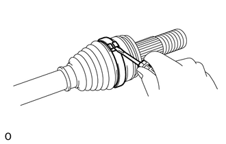
| (b) Using needle-nose pliers, disengage the 2 claws as shown in the illustration and separate the rear No. 2 drive shaft inboard joint boot clamp (for Type A). |
|
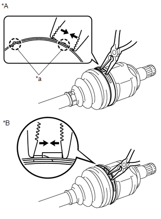
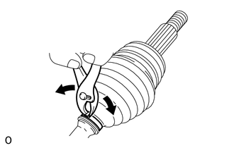
(c) Using needle-nose pliers, separate the rear No. 2 drive shaft inboard joint boot clamp (for Type B).
2. SEPARATE REAR DRIVE SHAFT INBOARD JOINT BOOT CLAMP
HINT:
Perform the same procedure as for the rear No. 2 drive shaft inboard joint boot clamp.
3. SEPARATE REAR DRIVE SHAFT INBOARD JOINT BOOT
(a) Separate the rear drive shaft inboard joint boot from the rear drive shaft inboard joint assembly.
4. REMOVE REAR DRIVE SHAFT INBOARD JOINT ASSEMBLY
(a) Remove the old grease from the rear drive shaft inboard joint assembly.
| (b) Put matchmarks on the rear drive shaft inboard joint assembly and rear drive shaft outboard joint shaft assembly. NOTICE: Do not use a punch for the marks. |
|
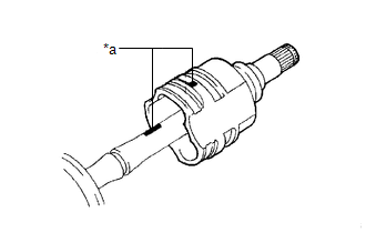
(c) Remove the rear drive shaft inboard joint assembly from the rear drive shaft outboard joint shaft assembly.
(d) Secure the drive shaft in a vise between aluminum plates.
NOTICE:
Do not overtighten the vise.
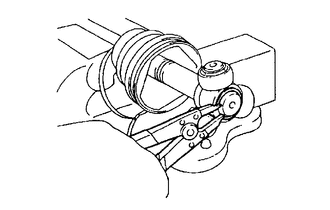
| (e) Using a snap ring expander, remove the shaft snap ring from the rear drive shaft outboard joint shaft assembly. |
|
| (f) Put matchmarks on the rear drive shaft outboard joint shaft assembly and tripod joint. NOTICE: Do not use a punch for the marks. |
|
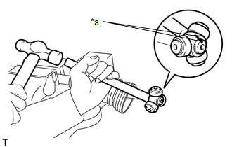
(g) Using a brass bar and a hammer, tap out the tripod joint from the rear drive shaft outboard joint shaft assembly.
NOTICE:
- Do not tap the rollers.
- Do not drop the tripod joint.
5. REMOVE REAR DRIVE SHAFT INBOARD JOINT BOOT
(a) Remove the rear No. 2 drive shaft inboard joint boot clamp, rear drive shaft inboard joint boot and rear drive shaft inboard joint boot clamp.
6. SEPARATE REAR NO. 2 DRIVE SHAFT OUTBOARD JOINT BOOT CLAMP
| (a) Using a screwdriver, separate the rear No. 2 drive shaft outboard joint boot clamp as shown in the illustration. |
|
7. SEPARATE REAR DRIVE SHAFT OUTBOARD JOINT BOOT CLAMP
| (a) Using pliers, separate the rear drive shaft outboard joint boot clamp as shown in the illustration. |
|
8. REMOVE REAR DRIVE SHAFT OUTBOARD JOINT BOOT
(a) Remove the rear drive shaft outboard joint boot clamp, rear drive shaft outboard joint boot and rear No. 2 drive shaft outboard joint boot clamp from the rear drive shaft outboard joint shaft assembly.
(b) Remove the old grease from the outboard joint.
9. REMOVE REAR DRIVE SHAFT DUST COVER
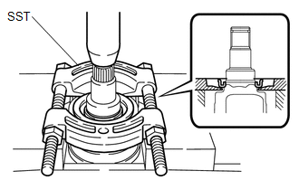
| (a) Using SST and a press, remove the rear drive shaft dust cover. SST: 09950-00020 NOTICE:
|
|
 Removal
REMOVAL CAUTION / NOTICE / HINT The necessary procedures (adjustment, calibration, initialization, or registration) that must be performed after parts are removed and installed, or replaced during rea ...
 Inspection
INSPECTION PROCEDURE 1. INSPECT REAR DRIVE SHAFT ASSEMBLY (a) Check that there is no excessive play in the radial direction of the outboard joint. (b) Check that the inboard joint slide ...
Other materials:
Lexus RX (RX 350L, RX450h) 2016-2026 Repair Manual > Exterior Panels / Trim: Rear Wheel House Plate
ComponentsCOMPONENTS ILLUSTRATION *1 NO. 6 ROCKER PANEL MOULDING PROTECTOR - - RemovalREMOVAL CAUTION / NOTICE / HINT HINT:
Use the same procedure for the RH side and LH side.
The following procedure is for the LH side.
PROCEDURE 1. REMOVE NO. 6 ROCKER PANEL MOULDING PROTECTOR ...
Lexus RX (RX 350L, RX450h) 2016-2026 Repair Manual > Sliding Roof Housing (for Panoramic Moon Roof): Removal
REMOVAL CAUTION / NOTICE / HINT The necessary procedures (adjustment, calibration, initialization or registration) that must be performed after parts are removed and installed, or replaced during sliding roof glass sub-assembly, sliding roof housing panel, sliding roof drive gear assembly, sliding r ...
Lexus RX (RX 350L, RX450h) 2016-{YEAR} Owners Manual
- For your information
- Pictorial index
- For safety and security
- Instrument cluster
- Operation of each component
- Driving
- Lexus Display Audio system
- Interior features
- Maintenance and care
- When trouble arises
- Vehicle specifications
- For owners
Lexus RX (RX 350L, RX450h) 2016-{YEAR} Repair Manual

0.0097