Lexus RX (RX 350L, RX450h) 2016-2026 Repair Manual: Removal
REMOVAL
CAUTION / NOTICE / HINT
The necessary procedures (adjustment, calibration, initialization, or registration) that must be performed after parts are removed and installed, or replaced during rear drive shaft assembly removal/installation are shown below.
Necessary Procedures After Parts Removed/Installed/Replaced| Replaced Part or Performed Procedure | Necessary Procedure | Effect/Inoperative Function when Necessary Procedure not Performed | Link |
|---|---|---|---|
| Rear wheel alignment adjustment | Calibration |
| |
| Suspension, tires, etc. (The vehicle height changes because of suspension or tire replacement) |
|
| |
| Rear television camera assembly optical axis (Back camera position setting) | Parking assist monitor system | for Initialization: for Calibration: | |
| Panoramic view monitor system | for Initialization: for Calibration: | |
| Initialize headlight ECU sub-assembly LH |
| | |
| Gas leaks from exhaust system*1 | Inspection after repair |
| |
*1: for RH Side
HINT:
- Use the same procedure for the RH side and LH side.
- The following procedure is for the LH side.
PROCEDURE
1. REMOVE TAIL EXHAUST PIPE ASSEMBLY (for RH Side)
Click here .gif)
2. REMOVE REAR WHEEL
Click here
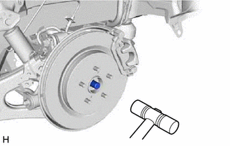
3. REMOVE REAR AXLE SHAFT NUT
Click here
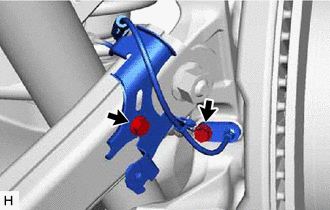
4. SEPARATE NO. 2 PARKING BRAKE WIRE ASSEMBLY
Click here
5. SEPARATE REAR SPEED SENSOR
| (a) Remove the 2 bolts, sensor clamp and rear speed sensor from the rear axle carrier sub-assembly and rear trailing arm assembly. NOTICE:
|
|
(b) w/o AVS:
| (1) Remove the 2 bolts and separate the rear speed sensor from the rear upper control arm assembly. |
|
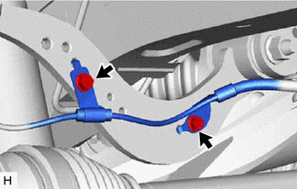
(c) w/ AVS:
| (1) Remove the bolt (A) and separate the wire harness from the rear upper control arm assembly. |
|
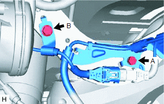
(2) Remove the bolt (B) and separate the rear speed sensor from the rear upper control arm assembly.
6. SEPARATE REAR FLEXIBLE HOSE
Click here
7. REMOVE REAR SUSPENSION ARM COVER
Click here
8. REMOVE REAR STABILIZER LINK ASSEMBLY
Click here
9. REMOVE REAR COIL SPRING
Click here
10. REMOVE REAR LOWER COIL SPRING INSULATOR
Click here
11. SEPARATE REAR UPPER CONTROL ARM ASSEMBLY
Click here
12. REMOVE REAR NO. 1 SUSPENSION ARM ASSEMBLY
Click here
13. DRAIN DIFFERENTIAL OIL
Click here
14. REMOVE REAR DRIVE SHAFT ASSEMBLY
| (a) Put matchmarks on the rear drive shaft assembly and rear axle hub and bearing assembly. |
|
| (b) Using a plastic hammer, separate the rear drive shaft assembly from the rear axle hub and bearing assembly. HINT: If it is difficult to separate the rear drive shaft assembly from the rear axle hub and bearing assembly, tap the end of the rear drive shaft assembly using a brass bar and a hammer. |
|
(c) Separate the rear drive shaft assembly from the rear axle carrier sub-assembly.
NOTICE:
- Do not damage the rear disc brake dust cover sub-assembly.
- Do not damage the rear drive shaft outboard joint boot.
- Do not drop the rear drive shaft assembly.
- Do not push the rear axle carrier sub-assembly towards the outside of the vehicle any further than necessary.
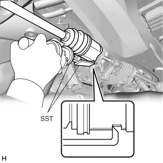
| (d) Using SST, remove the rear drive shaft assembly. SST: 09520-01010 SST: 09520-24010 09520-32040 NOTICE:
|
|
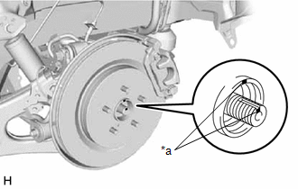
15. REMOVE REAR DRIVE SHAFT SNAP RING
| (a) Using a screwdriver, remove the rear drive shaft snap ring. |
|
.png)
 Components
COMPONENTS ILLUSTRATION *A w/ AVS *B w/o AVS *1 NO. 2 PARKING BRAKE WIRE ASSEMBLY *2 REAR FLEXIBLE HOSE *3 REAR SPEED SENSOR *4 WIRE HARNESS N*m (kgf*cm, ft.*lbf): ...
 Disassembly
DISASSEMBLY PROCEDURE 1. SEPARATE REAR NO. 2 DRIVE SHAFT INBOARD JOINT BOOT CLAMP (a) Secure the drive shaft in a vise between aluminum plates. NOTICE: Do not overtighten the vise. (b) Using needle ...
Other materials:
Lexus RX (RX 350L, RX450h) 2016-2026 Repair Manual > Luggage Speaker (w/o Rear No. 2 Seat): Inspection
INSPECTION PROCEDURE 1. INSPECT REAR NO. 3 SPEAKER ASSEMBLY (a) With the speaker installed, check that there is no looseness or other abnormalities. (b) Check that there is no foreign matter in the speaker, no tears on the speaker cone or other abnormalities. (c) Measure the resistance of the spe ...
Lexus RX (RX 350L, RX450h) 2016-2026 Repair Manual > Audio And Visual System (for 8 Inch Display): Display does not Dim when Light Control Switch is Turned ON
DESCRIPTION When the audio and visual system is activated with the light control switch in the tail or head position, before AVC-LAN communication is established, the multi-display assembly dims the display according to the illumination signal received via a direct line. After AVC-LAN communication ...
Lexus RX (RX 350L, RX450h) 2016-{YEAR} Owners Manual
- For your information
- Pictorial index
- For safety and security
- Instrument cluster
- Operation of each component
- Driving
- Lexus Display Audio system
- Interior features
- Maintenance and care
- When trouble arises
- Vehicle specifications
- For owners
Lexus RX (RX 350L, RX450h) 2016-{YEAR} Repair Manual

0.0118